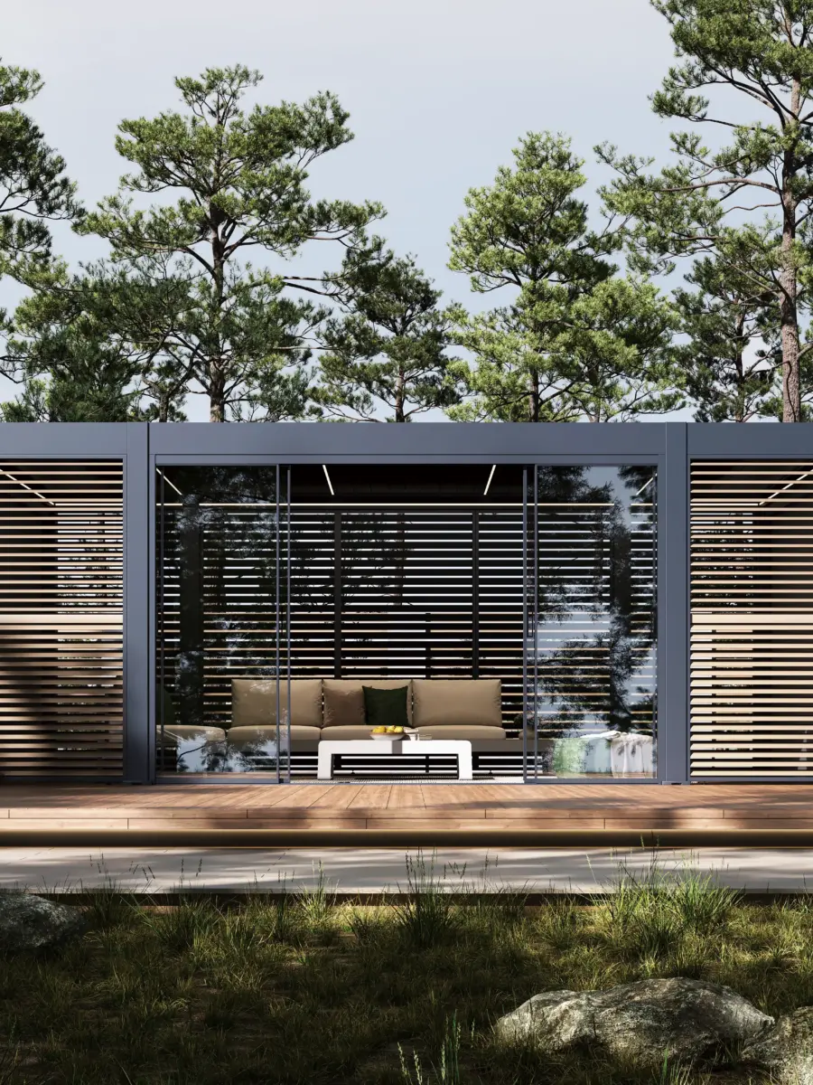
Plan an outdoor kitchen under a pergola by drawing the roof edge, post bases and working face of the complete cabinet run on one measured plan. Compare how the whole assembly works under the roof, along its edge or beside it, then check the appliance position and service connections in each layout. The difficult points usually emerge when a cabinet door opens across the route, a grill position ends up beneath an overhead element, or a fixed sink and the site’s drainage point sit on different levels.
Put the Pergola and Kitchen on One Site Plan
Draw the roof edge, posts and bases
Start with a plan the landscape designer, pergola installer and kitchen supplier can all use. Set one fixed reference on the building or paving and dimension everything from it. Draw the roof perimeter overhead with a broken line, the posts in plan and the base plates at paving level. Show the kitchen worktop outline, cabinet fronts and any overhang that reaches beyond the base below. Mark the major dimensions directly on the drawing so each team can tell whether a dimension ends at a post face, the edge of a plate or the end of the worktop.
For the comparison here, use the nominal 4 × 4 m, freestanding, four-post PRIME MAX motorized louvered pergola with one adjustable roof field. The selected version uses electric roof control. The product page lists aluminium post, beam and louver sections of 136 × 136 mm, 195 × 95 mm and 166 × 38 mm respectively. These are section sizes. Ask the installer for the selected assembly drawing to locate the actual roof edge, plate extents, post centers and underside of the beam. Find other structural layouts in the louvered pergola configurations.
The single roof field gives the project team four corners to coordinate. Because the nominal 6 × 4 m freestanding PRIME MAX uses six posts, check where each additional post can break up the planned approach along either of the two long sides. The structural comparison below shows why a cabinet run that worked beside a clear edge must be checked again when that edge gains an intermediate support. All three kitchen positions in this article use the four-post configuration.
 PRIME MAX aluminium bioclimatic pergola poolside scene with two roof bays and intermediate posts
Designed and created by the Outdoor Creation team.
Designed and created by the Outdoor Creation team.
- Intermediate posts. Check whether a proposed cabinet or approach crosses either additional base location.
Mark doors, paving levels and existing services
Mark building and gate openings in their usable positions. Plot the route between the kitchen, the main entry and the table or pickup point with furniture shown where it will actually stand. Put finished paving levels at the house threshold, the pergola posts and both ends of the cabinet run. If a step falls within a working route, record which people or carts use it at the busiest point of service. If applicable to the project, have the design team check the route against the relevant requirements. The U.S. Access Board guidance on accessible routes describes the components to review on covered U.S. sites.
Take a second pass with the installer and identify visible drain covers, existing water and power points, and any paving that can be lifted. Give each connection point an identifier and mark its level or wall height where measured. Photograph the threshold, the surface at each potential post and the area behind the proposed sink cabinet. Record missing data on the plan and assign someone to confirm it. A measured plan and these photographs let the same team revisit the layout when the equipment schedule or paving design changes.
Compare Three Positions for the Complete Kitchen
Place the complete kitchen under the roof
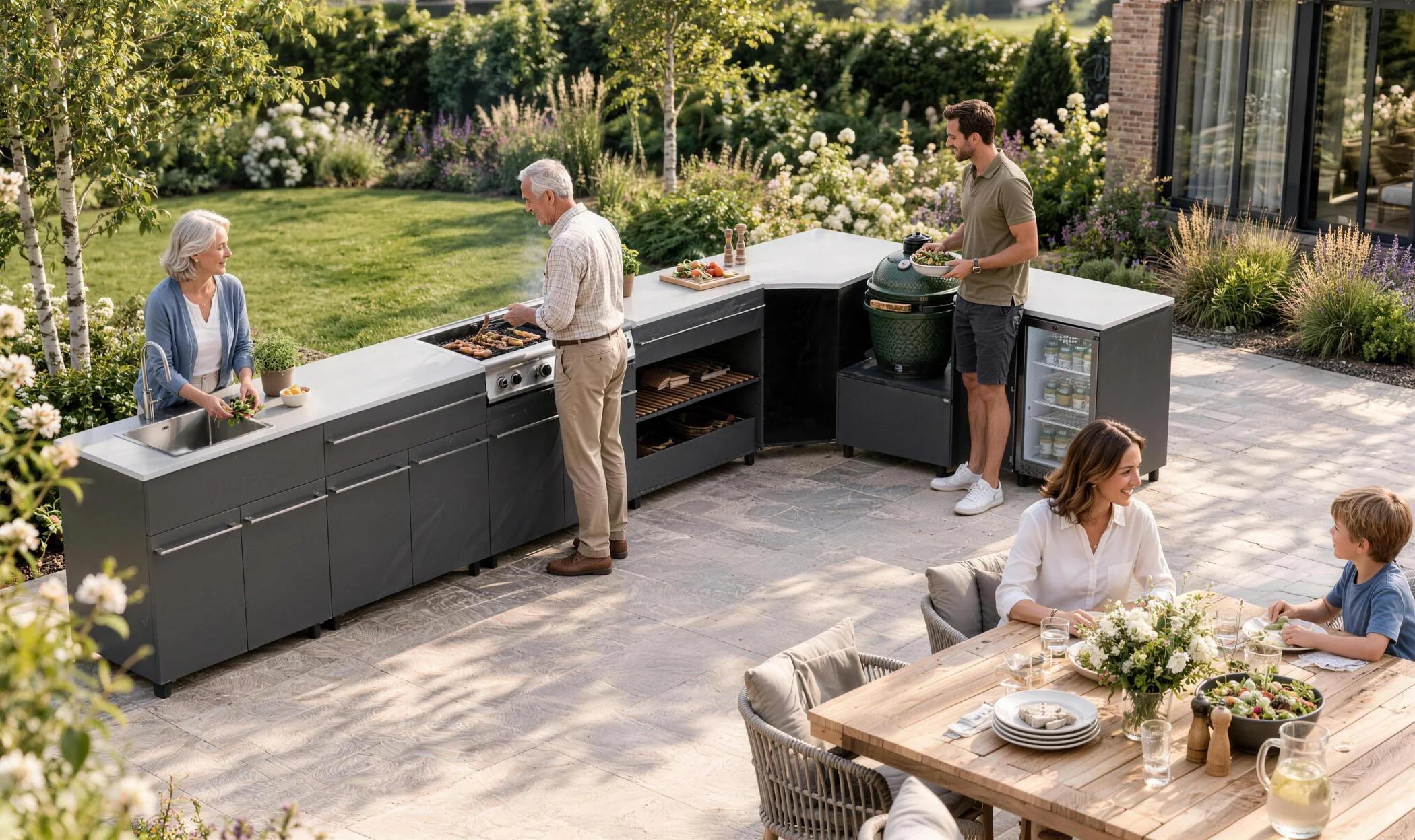
Begin with a single cabinet run and keep it together for all three tests. The example uses the galvanized steel AXIS outdoor kitchen in the straight Arrangement 4. Looking at the cabinet fronts, its order is A + F + B + D + A. The A end modules have open mesh shelving, F provides the lowered BBQ appliance position, B provides prep and storage, and D carries the sink. Added together, the listed module widths give a nominal straight cabinet footprint of 3,600 × 600 mm. Keep the faces, mesh ends and access to the sink in view when testing the placement.
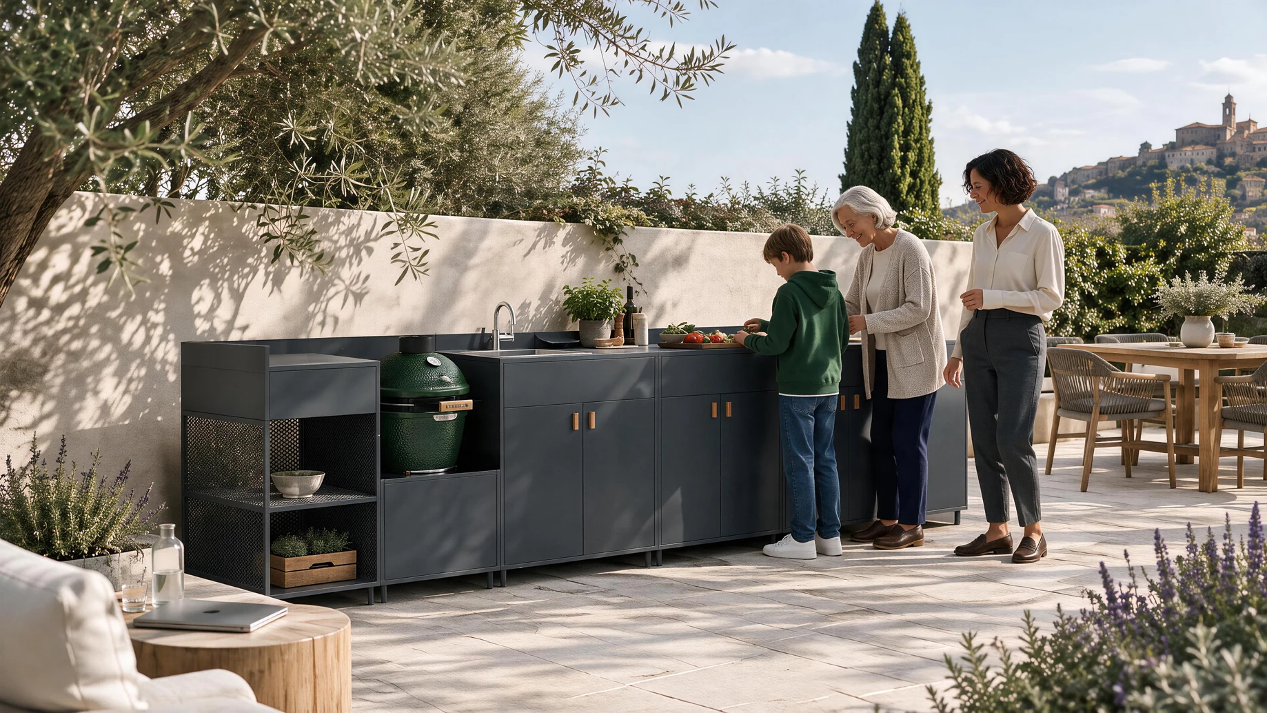 AXIS garden kitchen with open mesh shelving and a kamado position
Designed and created by the Outdoor Creation team.
- AXIS-A. Open mesh work and storage at the first end.
- AXIS-F. Lower BBQ appliance support.
- AXIS-B. Enclosed prep and storage cabinet.
- AXIS-D. Sink cabinet.
- AXIS-A. Open mesh work and storage at the opposite end.
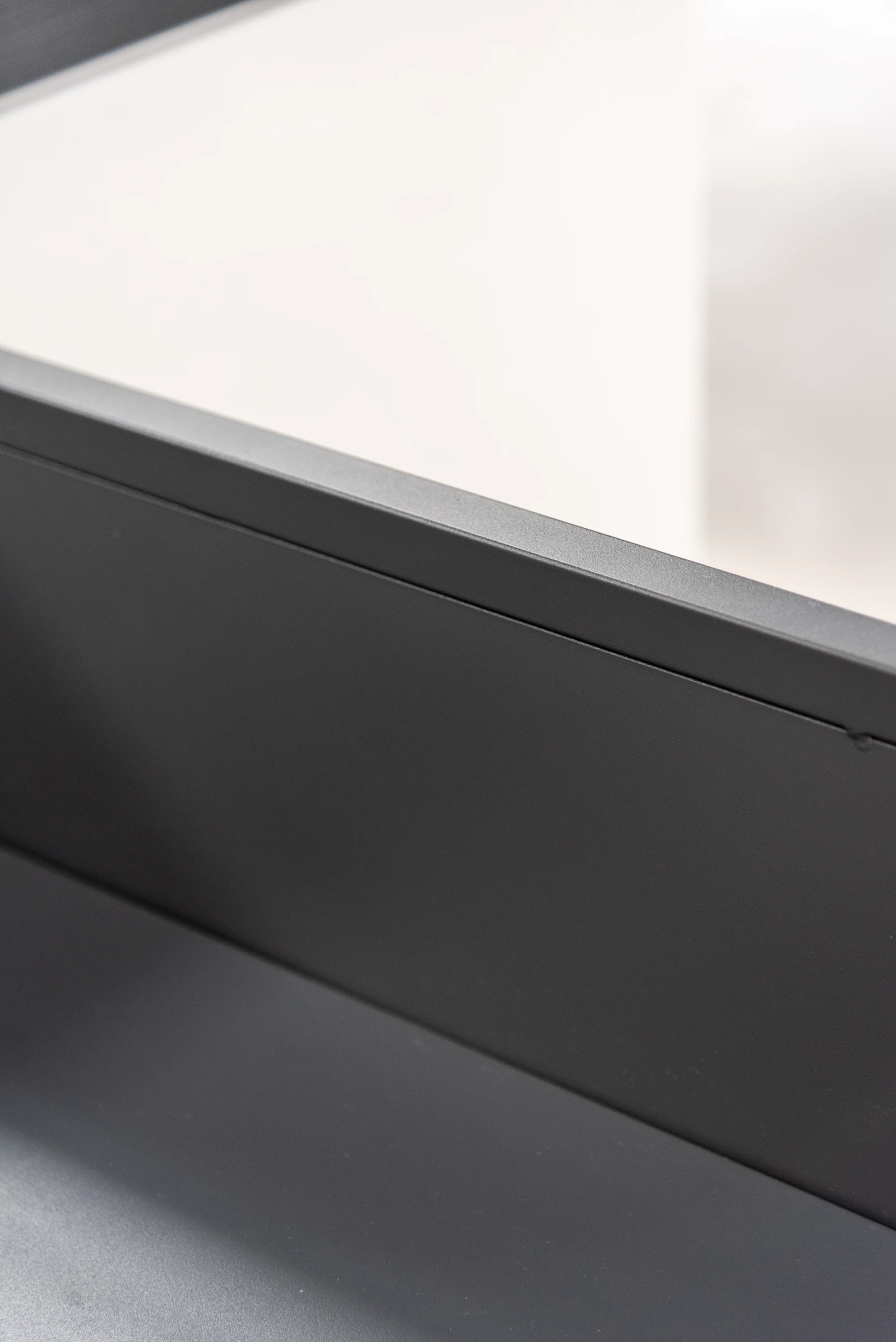 AXIS worktop edge and the line of the cabinet front
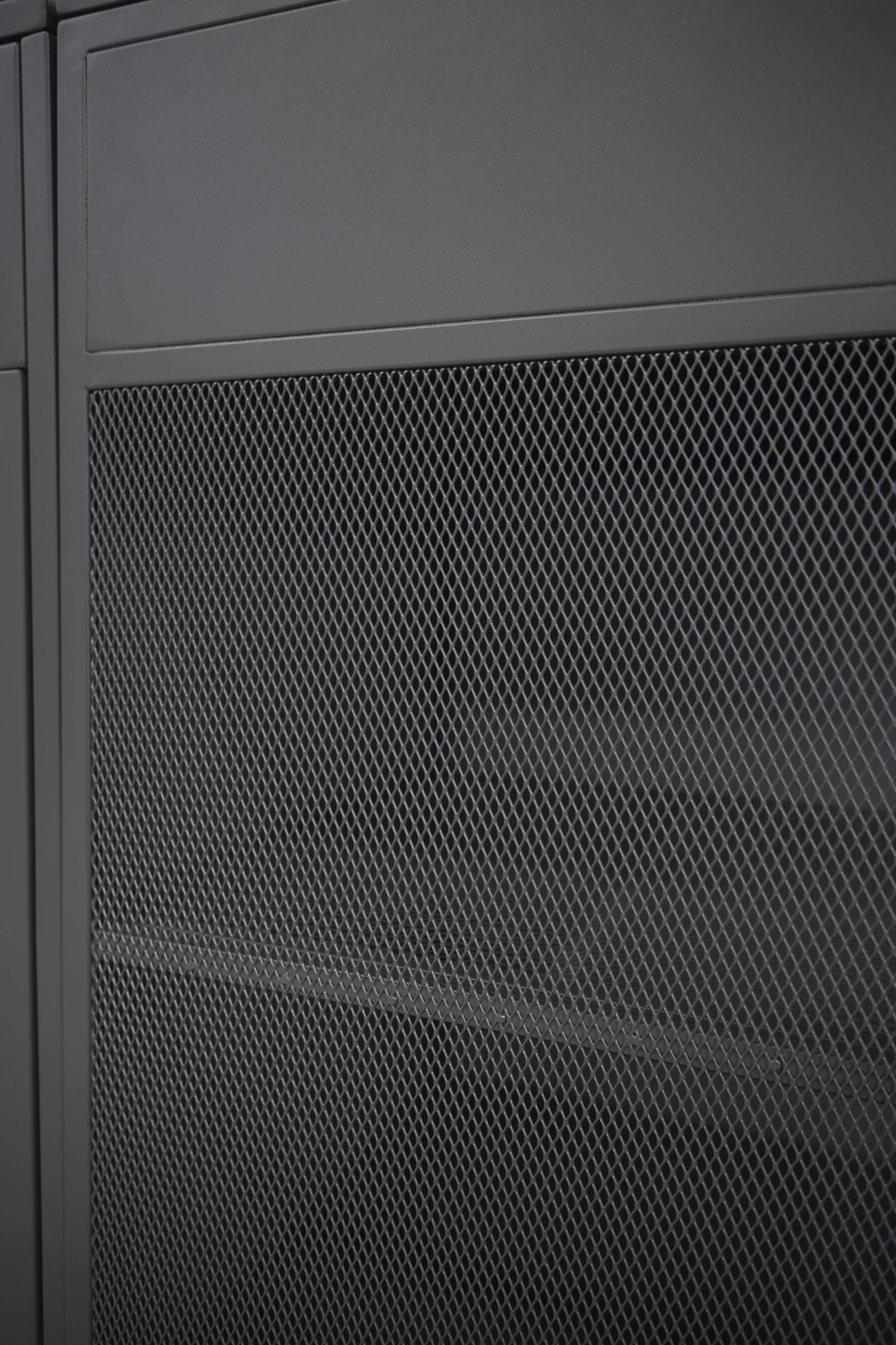 AXIS open mesh shelving at the end of the worktop
Set the run beneath the roof outline to test which work surfaces get shade through the intended hours of use. Stand on the working side on the drawing. Can a person move from washing to preparation while someone approaches for supplies? Trace cabinet openings and decide whether the sheltered working space is still useful with those doors open. The roof plan is only the first view. Add a section through F showing the overhead louvers, nearest beam and side conditions. Keep appliance installation at that site position pending the equipment review.
Align the complete kitchen with the roof edge
Move the full run parallel to the roof edge and show the offset between the edge and the front of the worktop. Put the intended handover point on the plan if the kitchen serves an outdoor dining area. Test that point against the actual approach from the house and the position of the nearest post. At this transition, changing the cabinet offset can change who has shade and where water drips or blows in. Ask where a person stops with a tray and which direction a cabinet door opens while someone is waiting.
Use the same furniture, path endpoints and marked services when comparing the roof-edge option with the under-roof option. The landscape designer can then distinguish a shorter handover route from one that merely has a wider-looking open area in the sketch. Verify shade and reflections during the period when people will work here. Check if the paving at the edge sends water back toward the cabinets or across the route. Carry the F position with the line of cabinets and review its side and overhead conditions in this placement too.
Place the complete kitchen beside the pergola
In the third position, set the full run next to the roofed area and let the pergola shade the dining or gathering space. This allows the team to consider a different overhead condition at F and may keep prep and serving traffic outside the space occupied by dining chairs. Verify where the work surface, cabinet doors and operator stand during use. The most likely tradeoffs are a longer carry, a different utility route and greater exposure of the kitchen to sun or blown rain. Mark these three changes on the plan so the choice can be reviewed when the actual equipment is known.
If the equipment review closes one option, compare the other positions using the same run. Homeowners, designers and a modular outdoor kitchen manufacturer for coordinated pergola and patio projects can then discuss the same cabinet schedule and roof geometry. Start with the modular outdoor kitchen cabinet systems when choosing a cabinet series. Once the series and combination are known, record the positions of the fixed modules and use the same complete outline across layout studies.
Designed and created by the Outdoor Creation team.
Designed and created by the Outdoor Creation team.
Designed and created by the Outdoor Creation team.
- A + F + B + D + A. Open mesh, lowered BBQ support, prep storage, sink, open mesh.
- Blue dashed route. Candidate approach. The solid blue line marks the cabinet working face.
- Four square markers. Corner post bases. The shaded field represents the motorized louver roof.
Test the Work Zone in Use
Open the cabinet doors and drawers
Walk a normal sequence on the plan. An operator approaches, takes something from an end shelf, uses the sink, opens a door and puts a tray down. At the same time, another person moves toward the dining area or returns through the gate. Draw the selected products’ opening envelopes and mark standing positions. Check the remaining clear opening beside posts, trim and any furniture. Review the service access needed at the back or side when a technician works at the cabinet, and check whether any panels need space to come off.
On AXIS, the open mesh end shelves and the contrasting pulls on the cabinet doors give two distinct access cues. Mark the open ends for reach and the enclosed units for door movement. A position can work well for someone grabbing a tray from the shelf and still leave too little useful space when the sink base is open. Photograph or sketch the intended working face, and transfer those access checks to the same cabinet edges on the plan.
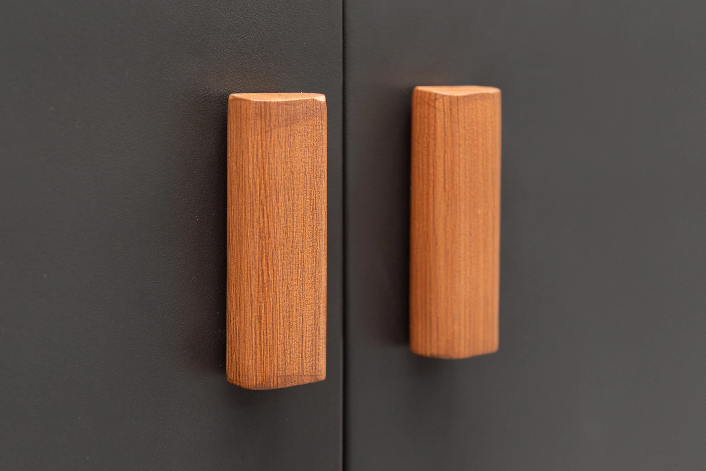
Check daylight, screens and the route past the posts
Study the planned operating conditions before deciding the work surface is well placed. Compare the motorized louvers in positions used during preparation and dining. Note the direction of low sun relative to the worktop and the way bright paving or glazing reflects light into the room or across the counter. For a layout that might later include a compatible side screen, overlay the screen in its stored and deployed positions. The main four-post example is open-sided. A screen, when separately selected, changes how someone approaches the opening and can affect the appliance review.
Designed and created by the Outdoor Creation team.
Designed and created by the Outdoor Creation team.
- Cabinet doors. Check the selected doors and the service approach with the fronts open.
- Optional screen. Verify the opening and route in the proposed screen state.
- Dashed route. Compare the paths the project team needs to keep open.
Run a separate check for a corner kitchen
When a project calls for a return, test the whole turn on the site plan. The complete L-shaped METRO Arrangement 4 gives a separate comparison. Its main working face and its return form an inside corner, so two people using adjacent sides can converge there. Show which direction a person approaches the sink, which face is used to open a door and whether the turn still works alongside a post. Compare the light on its 304 stainless steel worktop with the finish sample selected for the project. The catalog’s L-shaped arrangement shows the module relationship and provides the starting outline for that check.
 METRO garden kitchen with an L-shaped worktop and cabinet return
Designed and created by the Outdoor Creation team.
- METRO-G. Lower grill support and storage.
- METRO-D. Prep worktop and storage cabinet.
- METRO-A. Sink cabinet.
- METRO-L. Appliance housing at the turn.
- METRO-F. Low kamado support position.
- METRO-L. Appliance housing at the end of the return.
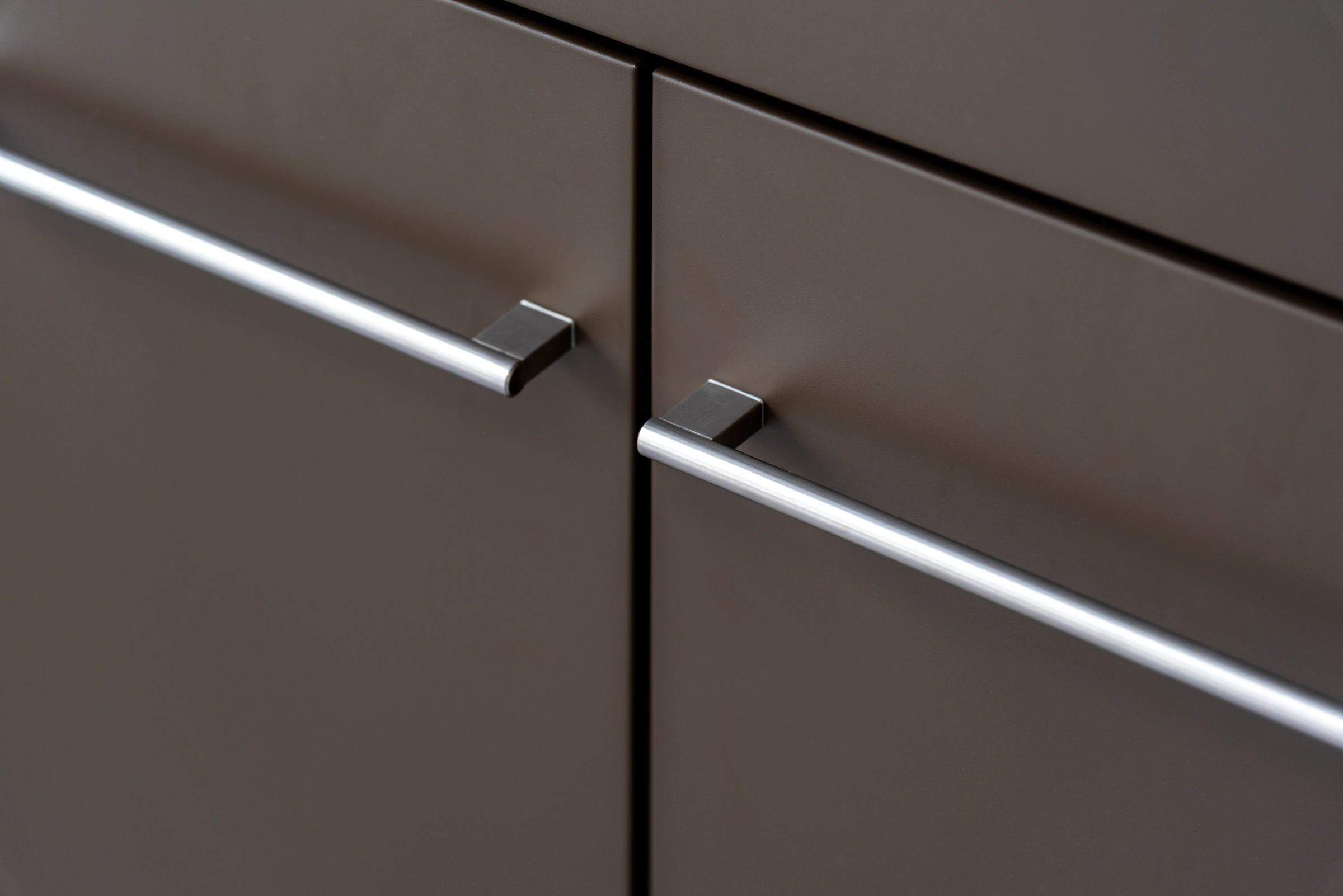
The access method also applies when you compare a compact NOVA cabinet layout, URBAN with a sintered stone worktop or ELITE with composite cabinet construction. Ask for the final configuration, actual access requirements and relevant finish samples for whichever series you specify. You can compare outdoor living product ranges to find the documentation for each structure and cabinet series.
Coordinate Water, Power and Equipment Locations
Separate roof runoff from sink waste
Show roof runoff, water supply and sink waste as distinct items. The U.S. EPA overview of stormwater runoff explains how water moves from rooftops and paved surfaces. On a patio drawing, identify the proposed roof discharge and where water will cross or leave the paving. For the sink, mark the supplier’s connection position, the proposed drain entry and the side from which the fittings can be reached later. Have the plumbing and drainage teams confirm lawful destinations, pipe routes, available levels and access with the actual products and site conditions.
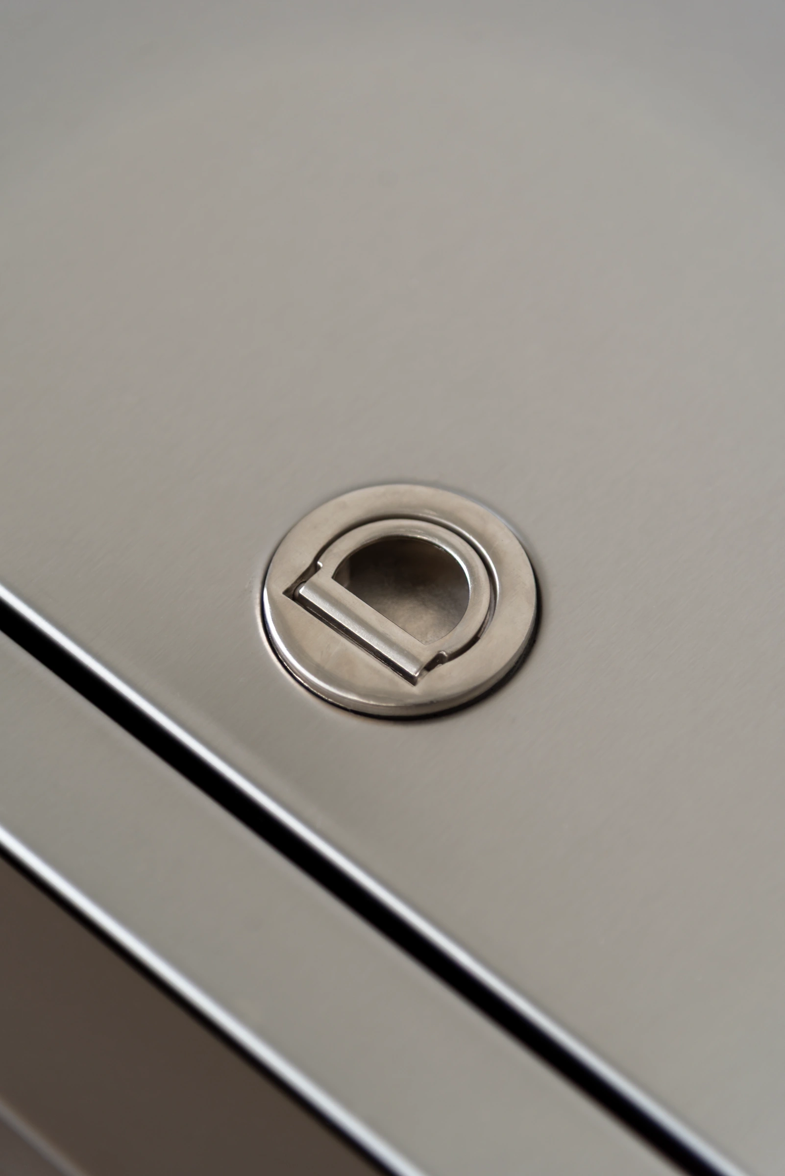
Walk both routes on site before committing the equipment and cabinets to a fixed location. Check whether a proposed crossing meets a footing, a site joint, an inspection cover or a threshold. Indicate the decision on the section if the crossing below paving has not been resolved. The METRO faucet and worktop lid show why wet work surfaces and moving covers need separate marks. Use the selected AXIS D data for the main layout’s actual sink connections.
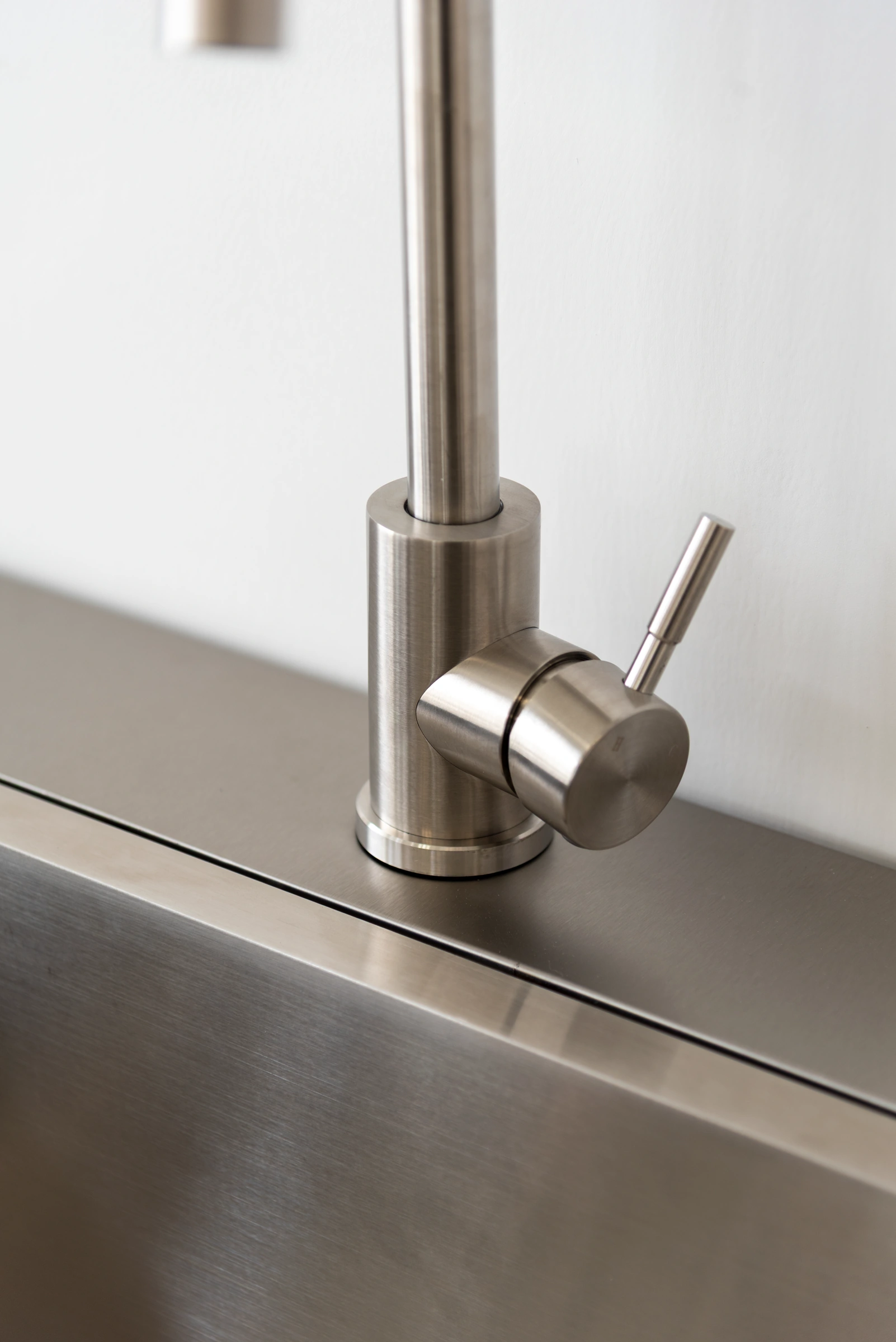
Mark appliance requirements and service connections
List the motorized roof and the kitchen equipment as separate service items. Give the electrical contractor the exact pergola motor and control documentation, the kitchen equipment schedule and the positions of the sink and roof discharge. Ask where the proposed connection, isolation and service access will be coordinated, and who approves routing near splash and exposure points. The Electrical Safety Foundation International guidance on ground-fault protection provides U.S. background on outdoor and wet-location hazards. The qualified project team determines the protection and installation requirements that apply on site.
Designed and created by the Outdoor Creation team.
- Roof runoff. Confirm the outlet, surface falls and discharge route.
- Roof motor. Confirm supply, isolation access and the approved motor connection location.
- Kitchen water. Confirm the supply point and access for service.
- Sink waste. Confirm the drainage destination and available connection.
- Kitchen power. Confirm equipment requirements, service access and the separately coordinated connection.
At the BBQ position, review the exact appliance’s installation instructions and the real setting from the same drawing. Show what is above it and on each side, including canopy beams, adjustable louvers, any planned screens and nearby walls. Check which fuels and equipment are permitted for that space, and identify any ventilation, access or protection requirements with the relevant project professionals. The U.S. Fire Administration outdoor fire guidance and the London Fire Brigade BBQ guidance provide general context. Appliance instructions and local project requirements determine whether and where the equipment can be installed.
Keep the F bay visible on every candidate plan and attach its unresolved appliance question to that location. If the chosen appliance is unsuitable beneath the roof or near an edge, recheck the proposed placement of the complete run. For the cabinet side of the decision, use the guide to confirming appliance integration before ordering. Record the updated equipment model, drawing revision and reviewer decision together.
Release the Layout for Drawings and Ordering
Assign each unresolved item to a reviewer
Hold a short review around one plan and at least one section through the working face and the nearest roof edge. Ask each reviewer to confirm a specific item and identify the current source. Put their answer beside the area on the drawing, then update the review record while the same information is in front of the group. An open point needs a named owner and a date for the next decision, especially if it could move a post, a fixed service point or the whole cabinet run.
| Reviewer | Question to answer before release | Record to share |
|---|---|---|
| Designer | Does the working face, including opened doors, leave a usable route at the times it will be busiest? | Measured plan showing travel and work zones |
| Structure and pergola team | Where do the base plates, roof edge and motor access sit for the selected four-post configuration? | Selected assembly drawing and site section |
| Kitchen supplier and installer | Can the complete cabinet run be assembled, opened, connected and reached for service in the chosen position? | Ordered cabinet schedule and connection locations |
| Electrical, plumbing and drainage teams | Which verified routes serve the roof and kitchen, and where is maintenance access available? | Coordinated service points and paving levels |
| Appliance reviewer | Does the exact appliance suit the selected overhead and side conditions at F? | Manufacturer instructions and project review outcome |
Check the coordinated drawing before ordering
Freeze the drawing version only after the team has resolved the items that affect siting. Confirm that the version used for pricing names the exact pergola size, mounting form and motorized control, and has the complete cabinet and equipment schedule attached. Cross-check the drawing against the installers’ current information before work begins. Ensure the proposed paving levels and connections still match the route you chose, and that any revised cabinet or structural information is carried into all copies of the coordinated plan.
Provide this package to the factory direct supplier of outdoor kitchens and louvered pergolas for contractors if the project calls for a review of the combined layout. Include the measured plan and section, working-face orientation, finish direction, appliance documents, delivery access and the questions each specialist has signed off. If additional manufacturing checks are needed, share the constraints with the outdoor structure manufacturing facility before finalizing the order. Keep the latest coordinated drawing available to the contractor when the job moves from design into installation.
Frequently Asked Questions
Can I put an outdoor kitchen under a pergola?
Yes, if the layout accommodates cabinet access and site services. Confirm whether the selected cooking appliance is permitted at that location under its installation instructions and local requirements.
Which kitchen tasks benefit most from shade?
Preparation and washing often benefit from shade during peak use. Map the roof edge and sun direction at those hours to see which parts of the worktop it covers.
Can I place a grill under the louvers?
Only if the selected appliance’s instructions and local requirements permit the actual overhead and side conditions. Have the project team verify the exact model and proposed position.
What should I measure around pergola posts?
Measure post and base plate extents, nearby trim, the door or drawer opening envelope and the width left for passage with cabinets in use.
Can an existing pergola work with new cabinets?
Yes, if the measured roof edge, bases, paving levels and existing services suit the complete cabinet layout. Verify appliance conditions and access before ordering.
Should roof runoff and sink waste share an outlet?
Plan them as separate routes. Have the drainage professional confirm where each may discharge and whether the local system allows any shared connection.
Where should kitchen utility connections be shown?
Show them on the shared plan and section beside cabinet service faces, paving levels and access points. Mark the pergola motor supply separately for a motorized layout.
What should the project team confirm before ordering?
Confirm the selected roof and cabinet configurations, exact appliances, connection locations, access and current drawing revision. Assign a reviewer and decision date to any outstanding item.
Send us your measured plan, preferred cabinet layout and equipment list. As a B2B manufacturer producing in our own factory, we can review your coordination questions, discuss custom options and help your project team identify what to confirm before ordering.
Materials, hardware, anchoring, service connections and order conditions depend on the selected products and site. Confirm custom options, equipment compatibility and final specifications with the project team before ordering.