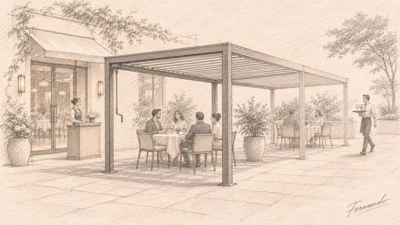
Plan a restaurant pergola around the tables your team can serve, the routes guests can use and the decisions staff make when the weather changes. Draw occupied chairs, queued guests, servers with trays and the required routes on the same terrace plan before fixing post locations. Then check how the space works when service pauses, guests move indoors or maintenance needs access. Use the confirmed configuration and local project requirements to set the final layout and operating plan.
Plan the Layout for an Occupied Terrace
A commercial pergola becomes part of the restaurant floor plan. When we review a restaurant pergola layout with designers and operators, four problems tend to affect where the roof and supports should go.
- Chairs change the plan. A passage that appears open on an empty drawing can narrow when guests sit down and servers pass with trays.
- Different routes share a door. Greeting, seating, carrying food and returning used dishes all bring people to the same threshold.
- The weather plan arrives late. A drawing may show shade before anyone has decided when to pause terrace service or where guests should go.
- Drainage and maintenance sit on separate drawings. A table can cover a point that needs inspection, and an outlet may discharge beside a busy doorway.
Map the Doors, Posts and Fixed Constraints
Start with a measured terrace plan. Add building openings, door movements, changes of level, fixed furniture, site boundaries, existing drains and the indoor space that serves the terrace. Mark the side where guests enter and the doorway staff use at the busiest shift. If both share one doorway, check what happens on each side when it opens and when someone is waiting. Record the fixed conditions separately from items the restaurant can move.
Draw roof coverage and post positions on separate layers. An area within the overhead footprint may have a post, an open door or a working stop at a corner. Carry the verified support arrangement of the selected configuration into the furniture plan. Our aluminum pergola systems for terrace planning have different control and support arrangements, so use the layout that corresponds to the actual selection.
Draw the Chairs in Use
Draw the chairs the venue intends to buy, including their occupied positions, and show where a guest shifts a chair to sit down. Add the position of someone taking an order at the table. This can change which table edges the team uses for serving and which tables belong in the busiest part of the terrace. Work with the furniture and door data the project team can verify, and leave open questions marked on the drawing before approval.
Record the meal periods the design needs to serve and look at the terrace from the positions guests actually occupy. Afternoon light or a busy arrival period may change which area the venue wants to open first. Make a note of each condition on the plan. A seating area can be part of the initial project, a later addition or a reserve area, depending on the space and how the restaurant intends to use it.
- Solid blue: guest movement between the dining room and occupied tables.
- Host queue: count waiting guests at the peak rather than drawing only the host stand.
- Dining zone: include chair backs in use and locate the posts on the site drawing.
- Long dashes: outbound service route from the staff door through the service station.
- Dots: return route for used plates to the service station.
- Check point: walk this shared area with chairs pulled out and a server carrying a tray.
Trace Guest, Serving and Return Routes
Walk the Guest Approach and Host Queue
Trace a first-time guest from the arrival point to the host and then to a table. Give the queue a place where it can form while other guests pass and staff use the door. Include a trip back to the building, with furniture and occupied chairs still in position. Decide where a host can see the arrival line and the tables without standing in the staff route. If a wait develops, the team should know where people can stand.
Ask the project team to verify which routes and access provisions apply, including the connection between the building and outdoor dining. The U.S. Access Board guide to accessible routes explains how exterior dining areas fit into the U.S. requirements. For a different example, England's pavement licence guidance covers certain temporary items on the public highway. Review the proposed structure, boundaries, permissions and local obligations with the responsible project professionals.
Test Service With Chairs Pulled Out
Walk the route with a serving tray from the door to the farthest likely table. Then walk a return trip with a tray of used dishes. Record where a server turns, passes a colleague or needs a surface to set the tray down. At each pinch point, measure from the inside face of the nearest fixed post or door edge to the occupied furniture position. Check a host or guest entering at the same time. The OSHA restaurant serving guidance identifies wet floors, blocked routes and visibility as hazards worth checking during the walk-through.
Use the pergola sizing and post position guide to interpret nominal dimensions and roof zones. Mark the exact references you measured between on the terrace plan. Where a turn interferes with serving, try moving the service station or changing how a table faces the route before reconsidering the support layout.
Test two routes first. Walk the longest run to a single table and the approach to the busiest doorway. Give each observation a location reference so the designer can return to the same point after a change. For example, record the guest-side door edge, the occupied chair position and the staff turning point as separate references. A second walk-through can then show whether the change resolved the conflict or moved it along the route.
Choose a Base Pergola Layout for the Terrace
When comparing pergola ideas for restaurants, start with a base unit that serves the first group of tables well. The three studies below keep the long side of each selected configuration fixed and test additional modules in its shorter direction. Read the expressions as sequences of nominal modules. Confirm actual lengths, the support plan and joint allowances on the approved project drawing. An aluminum pergola manufacturer for restaurant terrace design projects can review those fields against the site plan and service layout.
- Solid base and dark posts: verify the selected published stand-alone arrangement against the project drawing.
- Dashed outlines: conceptual depth increments. Keep the base width unchanged in each example.
- Measure the narrowest working gap on site with the chair occupied. Verify the door approach and actual post position separately.
PRIME PLUS: Extend From a 4 × 3.6 m Unit
The PRIME PLUS aluminum pergola in four- and six-post layouts includes a nominal 4 × 3.6 m freestanding configuration with four posts. For a compact entrance terrace, place the first dining group where staff can reach it from the service door. Locate the host position off that approach and keep the chair backs inside the planned seating area. With one additional module along the 3.6 m direction, the concept reads as 4 × (3.6 + 3.6) m. Check the route at the interface as well as at the door.
The two PRIME PLUS studies use the series' 116 × 116 mm post family. Consider its 116 mm joining kit for the extension and confirm the corresponding order configuration and connection detail. The first sketch fixes the source four-post frame and uses lighter linework for the continuation. Check the post locations, joints and access on the actual project drawing before setting the tables.
 PRIME PLUS dining setting with a white frame and overhead lighting.
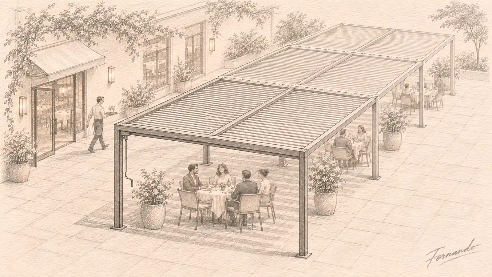
PRIME PLUS: Repeat a Wider 7.2 × 3.6 m Unit
For a wider restaurant frontage, the nominal 7.2 × 3.6 m freestanding PRIME PLUS configuration uses six posts and two louver fields across its width. The reference shows the middle support line. Use it to check which areas suit tables and which side offers a direct staff route. PRIME PLUS has manual and optional motorized roof control. The drawings use the manual reference, with the control position and staff access checked for the actual configuration.
In the second study, hold the 7.2 m side and test 7.2 × (3.6 + 3.6 + 3.6) m. Each nominal row keeps the two-field logic of the base unit. Plan where a server can see the next group, pause safely and return toward the service door. Have the project team check the joining arrangement, support locations and drainage for the selected build. Preserve the 3.6 m direction in the repeat even when the first row has a wider front.
 PRIME PLUS front view with two seating zones and a central post.
PRIME PLUS freestanding post layouts


PRIME PLUS dining and lounge settings


PRIME PLUS posts, roof and seating edges


PRESTIGE: Keep the 6 × 4 m Interior Open
The PRESTIGE motorized aluminum louvered pergola configurations include a nominal 6 × 4 m four-post freestanding layout. The catalog also shows a six-post option at the same nominal size. Use the four-post drawing for this study. Four corner supports leave the center open for table changes or a service path. This selection uses the 150 × 150 mm post family and a motorized roof. Keep the access and controls on the operating plan.
To study a deeper terrace, retain the 6 m side and test 6 × (4 + 4 + 4) m along the 4 m direction. The continuation marks show where further base units could sit. Specify PRESTIGE interfaces, support and drainage for the selected project separately from PRIME PLUS. In the drawing, reserve space for a clear connection between dining groups before adding tables to the farthest row.
 PRESTIGE beside a garden façade with slatted sides and an open approach.
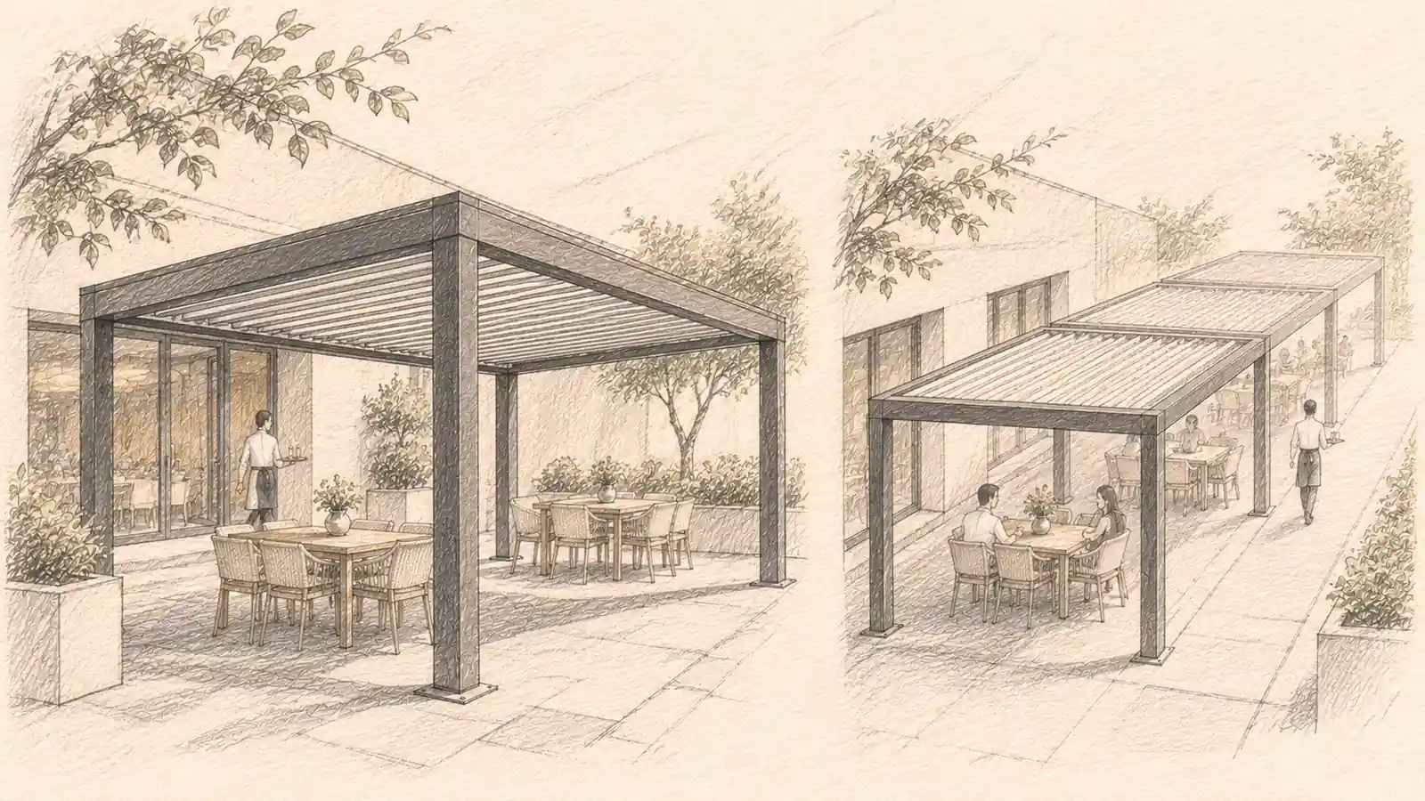
 PRESTIGE terrace setting showing the relationship between the opening, glazing and lounge area.
PRESTIGE freestanding post layouts


Plan for a Change in Weather
Compare Normal Service and a Paused Terrace
Take the wider PRIME PLUS terrace study and use the same roof, posts, tables and doors in both views. In normal service, mark where the host seats guests, where dishes arrive and where used dishes return. In the paused state, mark the tables where seating stops, the point where staff can speak to guests and the verified route indoors. Check the indoor reception point as well. A queue carried inside can interfere with the service doorway just when staff need it for communication and clearing.
Show roof and screen positions only as verified choices for the ordered system. Side exposure and floor conditions may affect some tables earlier than others. Test whether a section can pause while staff retain access to the other tables under the venue's plan. If the venue needs to clear the terrace, show who directs guests and who stops new arrivals at the host point.
Use one layout reference for both views so the team can point to the same doorway, seating group and support. Add the positions of any temporary signs in the paused state and write down where waiting guests go. After a practice walk, record how staff will communicate the change at the host point, the service door and the indoor destination. This is also a useful time to check whether movable screens or planters interfere with those actions.
- Solid blue: guest route. On a pause, lead guests to the receiving indoor area specified in the venue plan.
- Long dashes: staff route. Follow the venue plan for stopping service and moving the team indoors.
- Keep the doorway and indoor continuation clear. Confirm surface and route conditions before reopening.
Assign Stop and Reopen Decisions
Write the decisions on an operating sheet the shift lead can use. Take product operating limits from the applicable instructions, site triggers from the approved venue plan and relevant alerts from local weather information. Keep equipment operation distinct from the decision to seat guests. The National Weather Service lightning guidance calls for moving indoors to a substantial enclosed building when thunder is heard. Include a verified indoor destination and a clear instruction to stop terrace service in the venue's lightning plan.
| Operating state | Trigger and source | Decision owner | Action for guests and staff | Check before opening or restarting |
|---|---|---|---|---|
| Normal service | Scheduled shift and site opening checks | Opening lead | Confirm host position, service route and occupied seating. | Doorways, walking surface and equipment controls ready |
| Pause one area | Venue trigger for local exposure or runoff | Shift lead | Stop seating in the affected area and inform the host and servers. | Route, surface and discharge checks for the affected tables |
| Close the terrace | Venue closure trigger or applicable weather alert | Designated duty lead | Stop seating and direct guests and staff to the agreed indoor destination. | Venue restart criteria and applicable equipment checks |
| Reopen | Venue restart criteria met | Designated reopening lead | Tell the host and staff which tables can return to service. | Food service route, floor, drainage and confirmed equipment state |
- Assign a monitor before service and record the sources they use.
- The named shift lead uses the venue plan, relevant alerts and confirmed product operating instructions.
- Suspend seating as directed and use the designated indoor route and receiving area.
- Verify restart criteria, routes, floor condition, drainage and relevant equipment state.
- Record the decision and share it at shift handoff.
Put Drainage and Maintenance on the Plan
Trace Runoff to the Approved Discharge Point
Put the roof drainage outlet and the ground drainage system on the same drawing. Follow the confirmed outlet from the selected configuration to the proposed discharge destination. Check where water might meet the service door, a host queue or the path to the indoor waiting area. Mark how the ground slopes and who checks the receiving surface, drain and capacity. Our guide to how a louvered pergola drainage system works explains the route through the pergola. This terrace plan carries it through the site interface.
Repeat the check at every proposed connection between modules. Ask for the outlet locations, how the selected system handles water at the joint and how the site receives it. If rainwater would reach a frequently used threshold or collect where servers turn, assign the issue to the designer or installer for resolution. Keep the operating plan current when the discharge route changes.
Keep Access for Service and Inspection
Show the approach to the roof control, drain inspection point and any equipment that needs maintenance. Draw enough room for the verified access procedure and agree what furniture can be moved before the task. Where the position would be blocked during service, assign a separate access time and a place to put moved chairs. Record who closes the affected area and who confirms it can return to use.
Before handover, have the installer show the venue which elements are accessible, which checks the staff perform and when to call a service technician. Give that information to the people who open and close the terrace. An emergency route, a drainage route and a way to reach equipment have distinct purposes. Mark each on the appropriate drawing and resolve any place where they use the same strip of floor.
Hand the Layout and Operating Plan to the Venue
Work With Our Factory on a Site-Specific Design
We design and manufacture pergola systems in our own factory. For premium hospitality projects, we can develop a custom layout, assess whether revised aluminum profiles or new tooling are needed, and develop tooling within an agreed scope. We review the connection details, drainage and finish with your project team before sampling and production. Our pergola and outdoor structure manufacturing facility and custom aluminum pergola development and tooling pages explain the factory and development process.
For custom aluminum louvered pergolas for hospitality operators and designers, share the measured site plan, desired support locations, occupied furniture, doorway movement, runoff destination and priorities for weather and cleaning. Identify where the first unit goes and which direction the terrace may need to extend. That helps the team review whether a current configuration works or whether the agreed project scope needs new development. For adjacent spaces, review our outdoor living products for terrace projects against their own requirements.
Assign Owner, Designer and Installer Checks
Give the operator one dated plan with the verified unit, post positions, planned furniture and a drawing for each operating state. Have the designer record required routes, local approvals and project clearances. Have the installer confirm the selected mounting, drainage connections, controls and maintenance points. Have the venue name the people who decide when to pause and reopen. An unresolved item needs a responsible person and a date for confirmation before it becomes an operating assumption.
During the handover walk, mark anything that differs from the drawing while the team can still see it in place. A change to the service door, a new host stand or a relocated drain affects more than one drawing. Update the relevant sheet and confirm who received it. Keep the same revision at the venue and in the project record so future changes start from the right layout.
Where the site brief changes, compare the INTRO DUO manual louvered pergola with two roof sections or the PRIME MAX aluminum pergola frame configurations. Review their own product drawings for the relevant sizes, supports and controls. Confirm the scope of each commercial pergola system for the specific location and venue operating plan.
Frequently Asked Questions
Can a restaurant pergola stay open in rain?
Only when the venue’s operating plan and confirmed roof configuration allow it. Check runoff, side exposure, surface conditions and the route indoors before keeping the terrace open.
How should servers move around pergola posts?
Trace the route with occupied chairs and a loaded tray. Check door swings and post corners, then move tables or the service station where routes overlap.
How many tables fit under a restaurant pergola?
Set the count from a measured layout with occupied chairs, staff routes, door swings and post positions. Confirm capacity and clearances with the project team and local authorities.
Does closing louvers make the patio safe in lightning?
No. Follow the venue’s lightning plan, suspend terrace service and move guests and staff to a substantial enclosed building.
What accessories make sense for a hospitality pergola?
Consider lighting or confirmed side options where they solve a service problem. Check exact model compatibility, electrical needs, door access and furniture movement before selection.
Who decides when terrace service should pause?
Assign a shift manager or designated lead before opening. Give them the site’s written triggers and authority to stop seating and direct guests indoors.
Where should pergola runoff go on a terrace?
Show the confirmed outlet and drainage destination on the site plan. Keep discharge away from guest approaches, staff routes and door thresholds through the approved drainage design.
What should staff check before reopening the terrace?
Check the venue’s restart criteria, routes, floor and drainage, and the confirmed equipment state. A designated lead should approve reopening once the site meets those checks.
Materials, hardware, finishes, installation and order terms depend on the project. Confirm custom options and final specifications for the selected configuration, site and order.