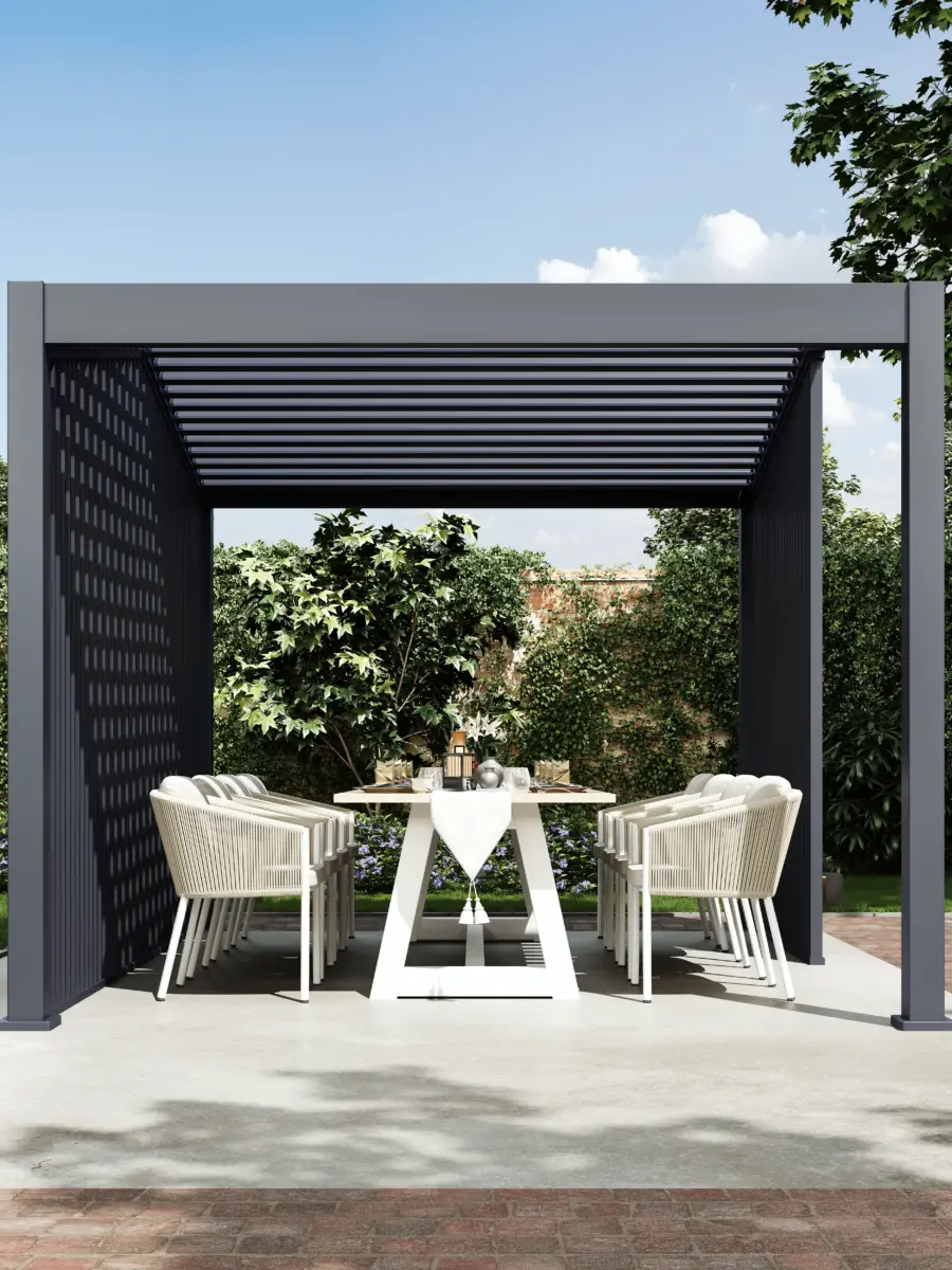
The difference between a freestanding and wall-mounted louvered pergola is not limited to the number of posts. Changing from a self-supporting structure to an attached configuration changes how roof loads, wind pressure, uplift, lateral forces and the pergola’s own weight are transferred into the ground and the adjacent building.
A freestanding pergola generally transfers loads through its beams, posts, base plates, anchors and supporting foundations.

A wall-mounted pergola divides the load path between its outer posts and a building-side connection. The wall, concrete beam, structural frame or other supporting element therefore becomes part of the project load path, even when it is not supplied by the pergola manufacturer.

For importers, distributors, contractors, outdoor living brands and project companies, this distinction affects site surveys, structural review, quotation scope, installation responsibility, waterproofing coordination, OEM or ODM customization and the documents required before production.
Direct answer: A freestanding louvered pergola transfers the structure’s actions primarily through its posts and ground connections. A wall-mounted louvered pergola transfers part of those actions into the supporting building and the remainder through its outer posts. The wall connection is therefore a structural interface, not a decorative mounting point. Anchor quantity, wall substrate, base condition, edge distance, embedment, reinforcement, installation accuracy, and the complete load path must be reviewed for the actual project.
What Is a Pergola Load Path?
A load path is the connected route through which forces move from the point where they act to the final supporting structure and foundation. FEMA’s building-code guidance uses the continuous-load-path principle to explain that structural members and connections must transfer loads through the structure to the foundation.
For a louvered pergola, the relevant actions can include:
- The dead weight of the aluminum frame, aluminum or steel louvers, electric motors, and accessories
- Downward roof actions from maintenance loads, rain accumulation, or other specified roof loading
- Wind pressure acting horizontally or vertically on the roof and the metal frame
- Uplift acting through the louvers, beams, posts, brackets and anchors
- Overturning effects created by horizontal forces acting above the supporting surface
- Additional loads created by heaters, fans, ZIP screens, glass panels, blinds, privacy systems or custom enclosures
The roof profile is therefore only one part of the system. Connections between louvers and beams, beam-to-post joints, wall brackets, base plates, anchors, concrete or masonry, foundations and the surrounding building all affect the completed load path.
The official
FEMA compilation of wind-resistant building-code provisions
provides further context on continuous load paths and transfer of uplift forces to foundations.
How the Two Structural Configurations Differ
| Structural Area | Freestanding Louvered Pergola | Wall-Mounted Louvered Pergola | B2B Project Implication |
|---|---|---|---|
| Primary support | Posts positioned around the pergola perimeter | Building-side connection plus outer posts | The attached version makes the existing building part of the structural review |
| Ground connection | All posts require suitable base support and anchoring | Outer posts require ground support while the building-side beam requires wall anchoring | Two different substrates and connection conditions may need to be designed |
| Lateral stability | Provided through the full frame, post layout, joints, base plates and foundations | Shared between the pergola frame, wall interface and outer-post bases | The supporting wall must accept the actions assigned to the attachment |
| Site information | Slab, footing, paving, underground services, levels and drainage route | All freestanding information plus wall construction, cladding, insulation and structural-member location | A wall-mounted inquiry normally requires a more detailed site survey |
| Waterproofing interface | Primarily coordinated at post outlets, bases and surrounding paving | Also requires coordination at the façade, flashing and building-side beam | The façade interface should be resolved before fabrication |
| Customization risk | Custom span, post relocation, and multi-bay layouts can change foundation reactions | The same changes can also alter the wall reaction and anchor distribution | OEM pergola engineering must review the complete configuration, not only outside dimensions |
What the TÜV Test Reports Show
TÜV Rheinland for Outdoor Creation's product reports provide directly comparable freestanding and wall-mounted test arrangements for three product platforms. In each pair, the nominal loaded area and calculated safety load remained the same, while the anchor distribution changed according to the installation form.
The reports use older internal names for some products. The 3.6 × 4 m INTRO PRIME files correspond to the Prime Plus report set, while the 4 × 8 m INTRO PRIME files correspond to the Prime Max report set. The figures below reproduce the tested arrangements rather than creating a universal installation schedule.
| Tested Sample | Installation Form | Net Weight | Anchor Arrangement in Report | Nominal Load | Safety Load | Measured Displacement |
|---|---|---|---|---|---|---|
| INTRO PLUS 3 × 4 | Freestanding | 140 kg | 4 ground plates 16 × M10 × 80 mm concrete anchors |
4,335.76 N | 5,202.91 N | 3 mm |
| INTRO PLUS 3 × 4 | Wall-mounted | 140 kg | 7 wall anchors + 8 ground anchors 15 × M10 × 80 mm total |
4,335.76 N | 5,202.91 N | 4 mm |
| INTRO PRIME 3.6 × 4 Prime Plus report set |
Freestanding | 162 kg | 4 ground plates 16 × M10 × 80 mm concrete anchors |
5,108.92 N | 6,130.70 N | 2 mm |
| INTRO PRIME 3.6 × 4 Prime Plus report set |
Wall-mounted | 155 kg | 7 wall anchors + 8 ground anchors 15 × M10 × 80 mm total |
5,108.92 N | 6,130.70 N | 2 mm |
| INTRO PRIME 4 × 8 Prime Max report set |
Freestanding | 420 kg | 6 ground plates 24 × M10 × 80 mm concrete anchors |
11,521.12 N | 13,825.34 N | 3 mm |
| INTRO PRIME 4 × 8 Prime Max report set |
Wall-mounted | 388 kg | 14 wall anchors + 12 ground anchors 26 × M10 × 80 mm total |
11,521.12 N | 13,825.34 N | 3 mm |
What this comparison establishes
The test records show that changing the installation form redistributed the stated anchors between the wall and ground while maintaining the same calculated load within each product pair. The figures document the tested samples on concrete substrates. They do not establish that the same anchor quantity, diameter or embedment is suitable for every wall, slab, footing, custom size, or installation location.
Why Anchor Quantity Alone Is Not an Anchor Design
An anchor is a structural connection element used to transfer loads into concrete, masonry, or another supporting material. The American Concrete Institute describes concrete anchors as cast-in or post-installed steel elements used to transmit loads into the concrete member.
This means that “16 anchors” is incomplete technical information. Wall-mounted pergola anchoring and freestanding pergola foundation design can also depend on:
- The calculated tension, shear and combined actions at each connection
- Concrete strength, thickness, reinforcement and cracked or uncracked condition
- Masonry unit type, grout condition and reinforcement where masonry is used
- Anchor diameter, material, approval, embedment and installation method
- Spacing between anchors and distance from slab or wall edges
- Base-plate and bracket stiffness
- Hole cleaning, drilling tolerance, torque and installation quality
- Corrosion exposure and compatibility between metals
- Local seismic, wind, snow and building-code requirements
The
American Concrete Institute’s anchorage resources
provide further information on anchors used to transmit loads into concrete. European buyers can also refer to the
European Organisation for Technical Assessment database
for European Assessment Documents relating to mechanical and bonded fasteners.
What Must Be Verified for a Freestanding Metal Pergola Foundation?
A freestanding structure avoids dependence on an exterior wall, but it does not eliminate structural site requirements. Every post reaction still has to pass through a base plate and anchor into a supporting slab, footing, structural deck or other approved foundation.
Paving stones, porcelain tiles, timber decking, composite boards, screed and thin surface slabs should not automatically be treated as structural anchoring substrates. The fixing must reach a supporting element that can resist the required tension, shear and overturning actions.
Before a freestanding pergola is approved, the project team should verify:
- Supporting element: slab, isolated footing, strip footing, structural roof or engineered platform.
- Material and dimensions: concrete strength, slab thickness, reinforcement and edge conditions.
- Post locations: compatibility with joints, edges, drainage, utilities and underground services.
- Level and tolerances: ability to align posts, beams, louvers and drainage routes without site improvisation.
- Water discharge: avoidance of concentrated discharge beside foundations or anchor locations.
- Finished-surface interface: treatment of tiles, decking, membranes and corrosion protection.
- Local approval: required structural drawings, permits or professional review.
An existing patio slab may appear solid but may not have been designed for pergola uplift or overturning. Its suitability should be confirmed rather than inferred from surface appearance.
What Must Be Verified for a Wall-Mounted Metal Pergola?
A wall-mounted aluminum pergola removes the inner row of posts, but it introduces a second structural substrate and a building-envelope interface. The wall-facing beam must be connected to an element capable of receiving the assigned reactions and transferring them through the building to its foundation.
The visible exterior surface may not be that supporting element. Common wall assemblies can include cladding, brick veneer, external insulation, rainscreen cavities, render, hollow masonry, timber framing, light-gauge steel framing, reinforced concrete or structural masonry.
The project team should identify:
- The wall build-up and location of the actual structural substrate
- Whether the connection passes through insulation, cladding or a cavity
- The position of concrete beams, columns, reinforced masonry, steel or timber framing
- Available edge distances, anchor spacing and embedment
- Whether the attachment introduces eccentricity through a thick façade build-up
- Flashing, sealant, thermal bridging and waterproofing responsibilities
- Potential conflicts with windows, doors, shutters, services and roof overhangs
- The party responsible for approving the wall connection
Structural masonry requires its own design and construction provisions. The
TMS 402/602 masonry code resources
illustrate why masonry should not be treated as equivalent to reinforced concrete solely because both appear solid at the surface.
Wall-interface rule: Brick veneer, façade panels, render, insulation and non-structural cladding should not be assumed to carry the pergola reaction. The designed connection normally needs to transfer loads to an identified structural wall, frame, beam or column, subject to project-specific engineering.
Why the EN 13561 Wind Result Does Not Define the Final Anchors
The reports assess identified pergola samples under EN 13561:2015+AC:2016 and record the test anchor arrangements. The same reports also state that the wind-resistance procedure is based on static loading and does not reproduce the repeated dynamic effects of turbulence in an actual installation.
The report further states that static pressure cannot be used by itself to define anchoring to the building. It also notes that the structural part to which the pergola awning is fixed is outside the standard’s scope.
This creates a clear evidence boundary:
| Evidence | What It Can Support | What Still Requires Project Review |
|---|---|---|
| EN 13561 test report | Performance of the identified sample under the stated test arrangement | Actual wall, slab, footing, anchors and site wind conditions |
| Manufacturer installation guidance | Product geometry, bracket locations and general fixing assumptions | Suitability of the local substrate and compliance with local requirements |
| Project structural design | Site-specific reactions, foundation and anchoring requirements | Correct installation and verification during construction |
The
BSI overview of EN 13561
provides the wider standard context. Outdoor Creation’s guide on
EN 13561 and louvered pergola performance
explains the test framework, while the separate
pergola load-rating guide
owns the interpretation of N/m², kN, kg/m², PSF and Beaufort values.
How Custom, OEM and ODM Metal Pergolas Change the Connection Review
Standard anchor layouts should not be carried unchanged into every custom pergola. OEM pergola engineering and ODM pergola development can change the load path even when the overall appearance remains similar.
Changes requiring review can include:
- Increasing the span or projection
- Removing, moving or adding posts
- Changing from a freestanding to an attached louvered pergola
- Adding a second or third roof zone
- Adding ZIP screens, glass doors or fixed side panels
- Changing beam, post or bracket profiles
- Adding motors, heaters, fans or lighting
- Installing on a rooftop, podium slab or unusual foundation
- Connecting through external insulation or façade systems
A custom pergola anchoring proposal should therefore be linked to an approved drawing revision and site information. The
custom aluminum pergola OEM and ODM development process
explains how drawings, BOMs, samples, and production approvals should be controlled before manufacturing.
Information a B2B Buyer Should Provide Before Quotation
A pergola manufacturer or supplier cannot determine reliable pergola anchoring requirements from a size request alone. Before requesting a freestanding or wall-mounted quote, the buyer should provide:
- Installation type: freestanding, wall-mounted, multi-bay, rooftop or another configuration.
- Exact dimensions: outside size, projection, height, roof zones and post positions.
- Project location: country, region, elevation and known environmental exposure.
- Ground condition: slab, footing, deck, paving, podium or roof structure.
- Wall construction: concrete, masonry, framing, insulation, cladding and available structural drawings.
- Site photographs: including wall interfaces, ground edges, openings, services and drainage.
- Accessories: screens, glass, panels, lighting, heaters and other components affecting the complete system.
- Local requirements: design loads, permits, engineering documents and language requirements.
- Customization scope: standard supply, private label, OEM adaptation or ODM development.
- Responsibility allocation: party providing site engineering, anchors, foundations, installation and approval.
The
pergola installation, site-requirement and permit guidance
provides additional questions for patios, rooftops, exterior walls and other installation conditions.
How Responsibilities Should Be Divided
| Party | Typical Information or Work | Risk If Responsibility Is Undefined |
|---|---|---|
| Pergola manufacturer or factory | Product drawings, weights, tested configurations, bracket locations, general installation guidance and available reports | The installer may use assumptions that do not match the supplied system |
| Buyer, distributor or project company | Accurate site information, target market, project requirements and appointment of local professionals where needed | The product may be manufactured before critical site constraints are identified |
| Structural engineer or qualified designer | Site actions, supporting-wall review, foundation design, anchor selection and local code assessment | A standard test arrangement may be applied to an unsuitable substrate |
| Installer | Verification of dimensions and substrates, approved anchor installation, alignment, sealing, commissioning and records | Correct drawings may still result in an incorrect completed installation |
| Local authority or building owner | Permits, property restrictions, approvals and acceptance requirements | The installed pergola may not satisfy local or contractual obligations |
Is a Wall-Mounted Pergola Automatically Cheaper?
Removing two or more posts can reduce some frame components, but a wall-mounted pergola is not automatically the lower-cost project.
The attached configuration may add:
- A more detailed wall and façade survey
- Project-specific wall brackets or spacers
- Structural review of the existing building
- More complex anchor selection and installation
- Flashing, sealant and waterproofing work
- Coordination around insulation, cladding, openings and services
- Greater installation risk if the concealed wall construction is unknown
A useful quotation should therefore compare the entire project scope rather than only pergola frame weight or post quantity.
Outdoor Creation’s current
INTRO PLUS motorized aluminum louvered pergola
and
PRIME MAX heavy-duty aluminum pergola
pages show both freestanding and wall-mounted commercial configurations. Applicable dimensions, current specifications, and technical-document coverage should be confirmed for the actual order.
How a Manufacturer Should Present Anchoring Information
A professional aluminum pergola manufacturer, louvered pergola supplier, company, or brand should not publish one anchor count as a universal instruction for every project.
Useful technical information should identify:
- The exact product model and drawing revision
- Freestanding or wall-mounted configuration
- Tested or assumed supporting substrate
- Base-plate and wall-bracket geometry
- Loads or reactions used for connection review
- General anchor assumptions and clear limitations
- Items requiring local structural confirmation
- Changes requiring renewed OEM or custom engineering review
Buyers assessing technical capability can review the guide to
evaluating a louvered pergola manufacturer and supplier
.
Information about production, assembly, quality control, packing and OEM/ODM coordination is available on the
outdoor metal pergola manufacturing facility
page.
The Practical Selection Rule
A freestanding pergola is not structurally independent of the site; it depends on suitable ground support and foundations. A wall-mounted pergola is not simply a freestanding model with fewer posts; it depends on both the ground and an identified building structure.
The correct choice should be based on five questions:
- Where will gravity, wind, uplift, and lateral actions be transferred?
- Are the wall, slab, or foundations suitable for those reactions?
- Does the proposed anchor system match the actual substrate and geometry?
- Do the product drawings and evidence correspond to the quoted configuration?
- Which party is responsible for site engineering, installation and local approval?
For global B2B buyers, the most reliable decision is not the layout with the fewest posts or the lowest initial quote. It is the configuration whose complete load path, supporting substrates, responsibilities and documentation can be clearly identified before production begins.
Review Your Outdoor Pergola Installation Configuration
Share the project location, dimensions, site photographs, wall construction, ground condition, installation type, accessories and available structural information. Outdoor Creation can coordinate relevant product drawings, tested-configuration references and manufacturing information for project review.
Technical note: The anchor quantities and loads in this article reproduce identified TÜV test arrangements. They are not universal installation instructions. Final foundations, wall connections, anchor selection, waterproofing and local approvals must be determined for the actual pergola configuration, supporting substrates, project loads and installation jurisdiction.