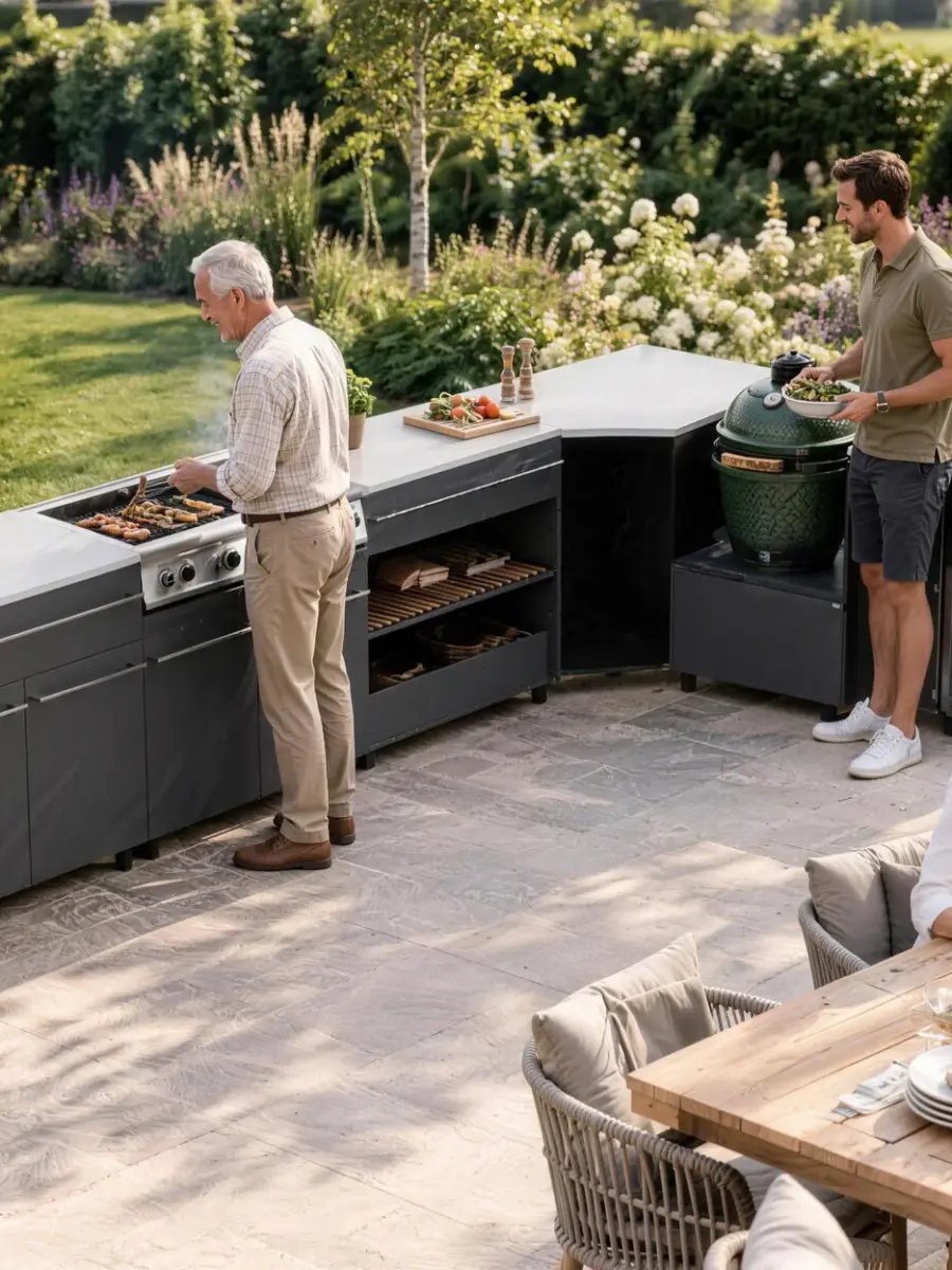
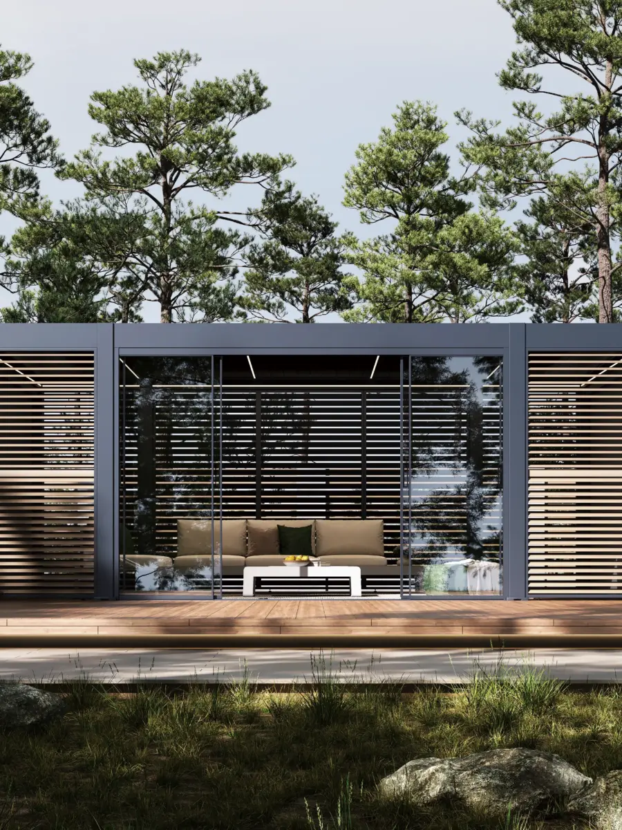
To specify outdoor kitchen modules, record cabinet width, depth and height separately from finished worktop height, the assembled layout and the openings required by each selected appliance. A module’s external dimensions do not establish an appliance cutout or its operating clearances. This guide uses NOVA and METRO examples to show how buyers, designers and installers can compare the right dimensions and assemble a traceable specification for a modular outdoor kitchen.
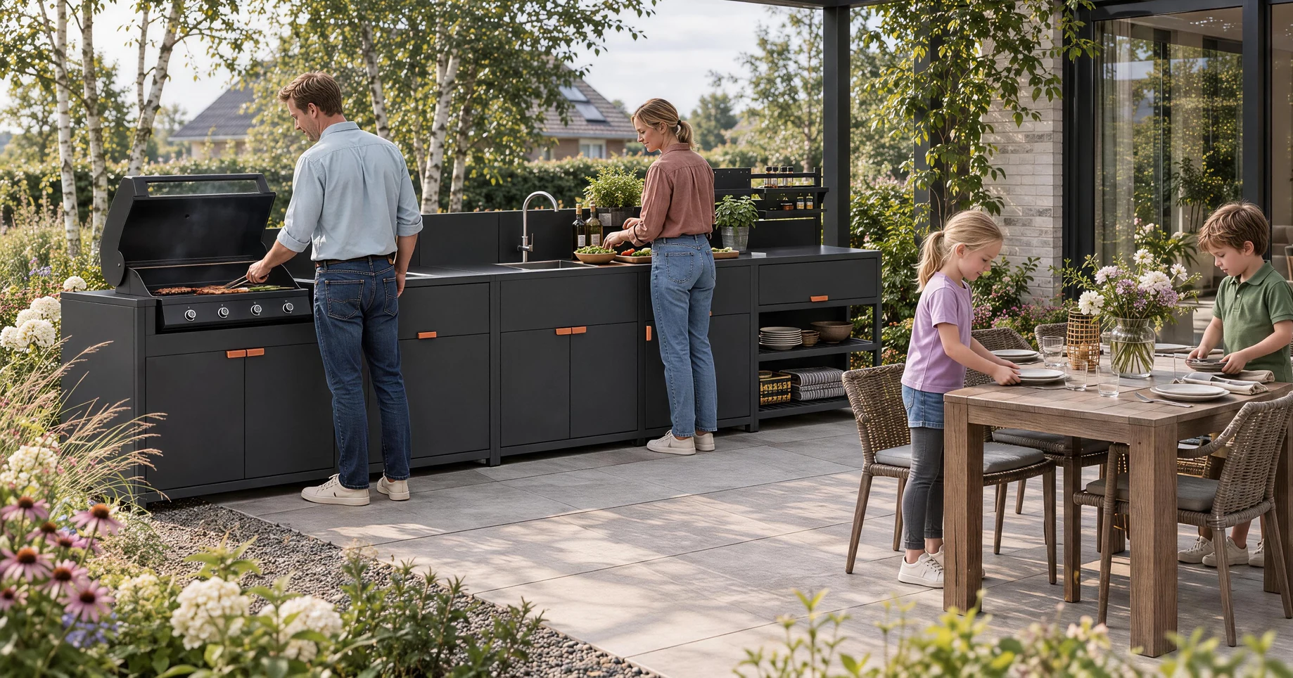 NOVA outdoor kitchen with distinct worktop, back-panel and appliance levels
Read the Right Dimension Before Comparing Modules
Separate the module envelope from the assembled kitchen
A module envelope describes one identified cabinet or unit. An assembled kitchen has another outline, determined by its module order, corners and finished details. Start with the selected modular outdoor kitchen systems with series-specific module dimensions, then identify each module by series and code. A list saying “sink, storage and grill” explains the functions but leaves the geometry unresolved.
For example, the width of a sink cabinet belongs to that cabinet, while the length of a complete run belongs to the configuration drawing. Adding a return also introduces a second direction. Neither a product photograph nor a row of cabinet widths establishes the finished outline by itself. Our guide to planning outdoor kitchen modules by function and appliance helps identify the required functions before their dimensions are recorded.
Keep the appliance as its own object. Its external body, installation opening and moving parts may extend beyond different reference points. Naming these objects first makes later comparisons useful: the buyer can see which figure describes the cabinet, which describes the equipment and which describes the space around the assembled kitchen.
Define width, depth, height and measurement references
Show width, depth and height directions on the drawing rather than relying on the order of three numbers. Use the same front view and reference surfaces when comparing modules. A depth measured to a cabinet body cannot be compared directly with a depth that includes a handle, rear panel or another projection unless that difference is identified.
| Dimension object | Record with the value | Main reference | Common confusion |
|---|---|---|---|
| Module envelope | Series, code and W/D/H directions | Current module drawing | Treating outside width as an appliance opening |
| Worktop height | Finished surface and floor reference | Selected assembly detail | Reading the top of a rear panel as the working level |
| Back-panel or rack height | Highest included element | Module elevation | Interpreting two heights as an adjustment range |
| Appliance interface | Exact model, opening and support | Applicable equipment and fabrication drawings | Using appliance body size as cutout size |
| Finished kitchen outline | Configuration, ends, corners and projections | Dimensioned assembly plan | Adding widths without resolving corner geometry |
| Operating or service space | Moving part, access direction and requirement | Equipment documents and site plan | Assuming a clear front elevation proves usable access |
State the condition in which the dimension applies. A finished assembly, a bare cabinet and a cabinet with a particular leg setting are different measurement states. If the available document does not identify the state, record the question for clarification before using the number to establish an adjoining level.
Distinguish Worktop, Back-Panel and Appliance Support Heights
Read separate heights on the same module
The NOVA galvanized-steel kitchen modules with separate worktop and back-panel heights show why one height field is often insufficient. NOVA-A is listed at 600 × 600 × 900/1100 mm. The illustrated working surface is at 900 mm and the rear panel reaches 1100 mm. The slash separates two elevations; it does not describe a height-adjustment range.
NOVA-C makes the distinction more visible. Its listed dimensions are 800 × 600 × 900/1300 mm: the preparation surface and the upper rack occupy different levels. A buyer comparing 1300 mm with another cabinet’s 930 mm worktop would be comparing different objects. A clearer schedule gives the worktop and rack their own columns, with the corresponding reference surface beside each.
- Worktop height. The 900 mm label ends at the worktop, rather than the rack.
- Overall rack height. The 1300 mm label ends at the top of the rack. It is not an adjustable height range.
- Outer width and depth. The 800 × 600 mm outline describes the selected module; usable surface and operating space need separate records.
This distinction also helps during site coordination. A rack or rear panel can affect the relationship with a window, wall feature or another fixed object even when the working surface remains lower. Check those relationships on the actual site elevation. The illustrated product heights do not establish an installation clearance around the appliance or the completed kitchen.
Check the completed appliance and working level
A lowered cabinet provides another height object: the equipment support level. NOVA-E is listed at 755 × 600 × 725 mm, while METRO-G is 900 × 630 × 730 mm. Those figures describe the low cabinet forms. They do not give the cooking surface, control position or highest point of whichever appliance is placed above them.
The same principle applies to kamado supports. NOVA-F separates a 415 mm low platform from a rear-panel height of 1100 mm. As a further example, the AXIS low-platform kamado module with a raised rear panel lists AXIS-E at 600 × 600 × 455/1030 mm. Each pair describes different points on its own module, with no implied interchangeability between the series.
A height note should also say whether a loose or removable part is included. For example, a closed countertop lid and an open lid occupy different envelopes even though the underlying cabinet has not moved. Record the normal working condition and the separate opening movement rather than extending one height label to cover both.
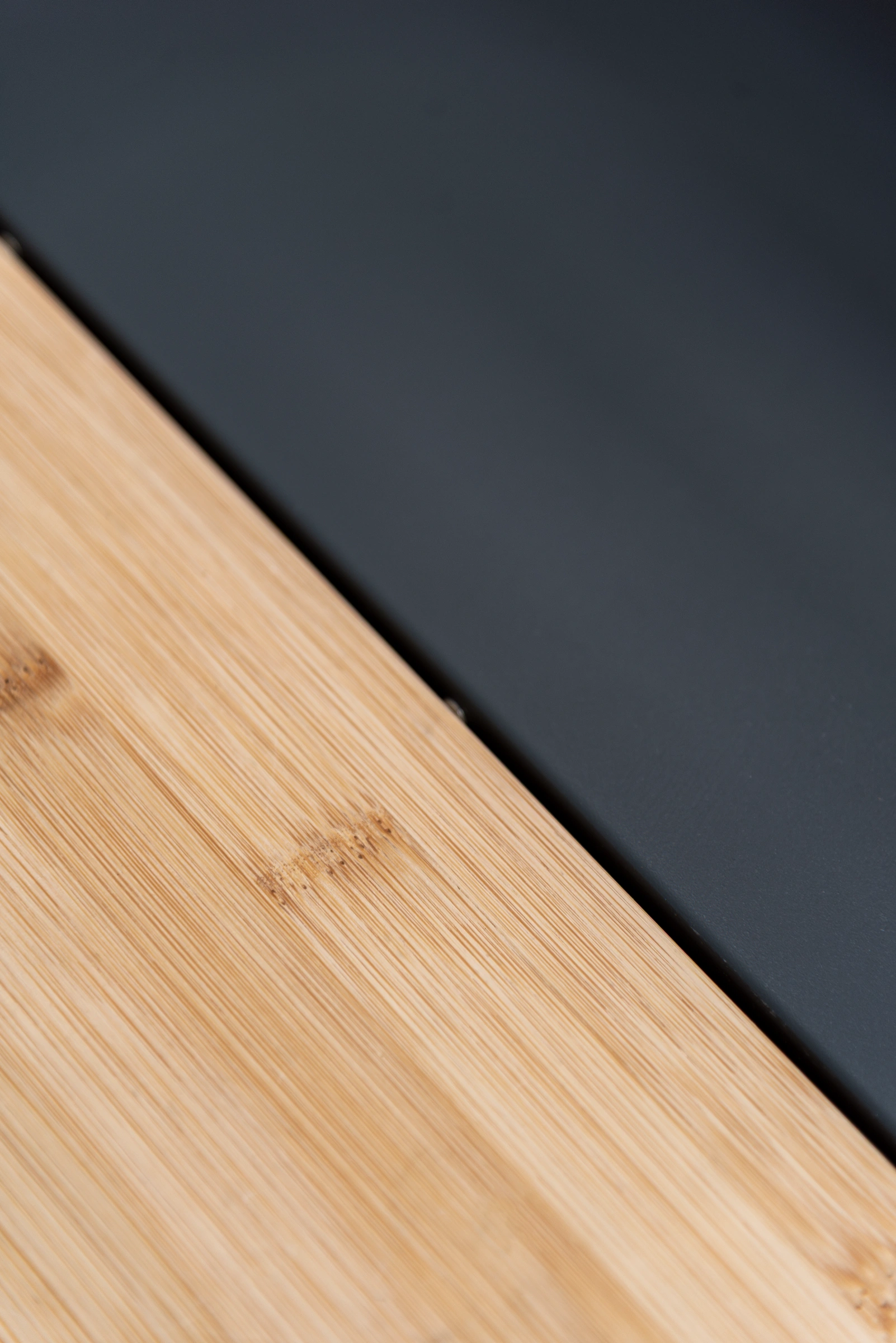 NOVA preparation surface and adjoining finished edge
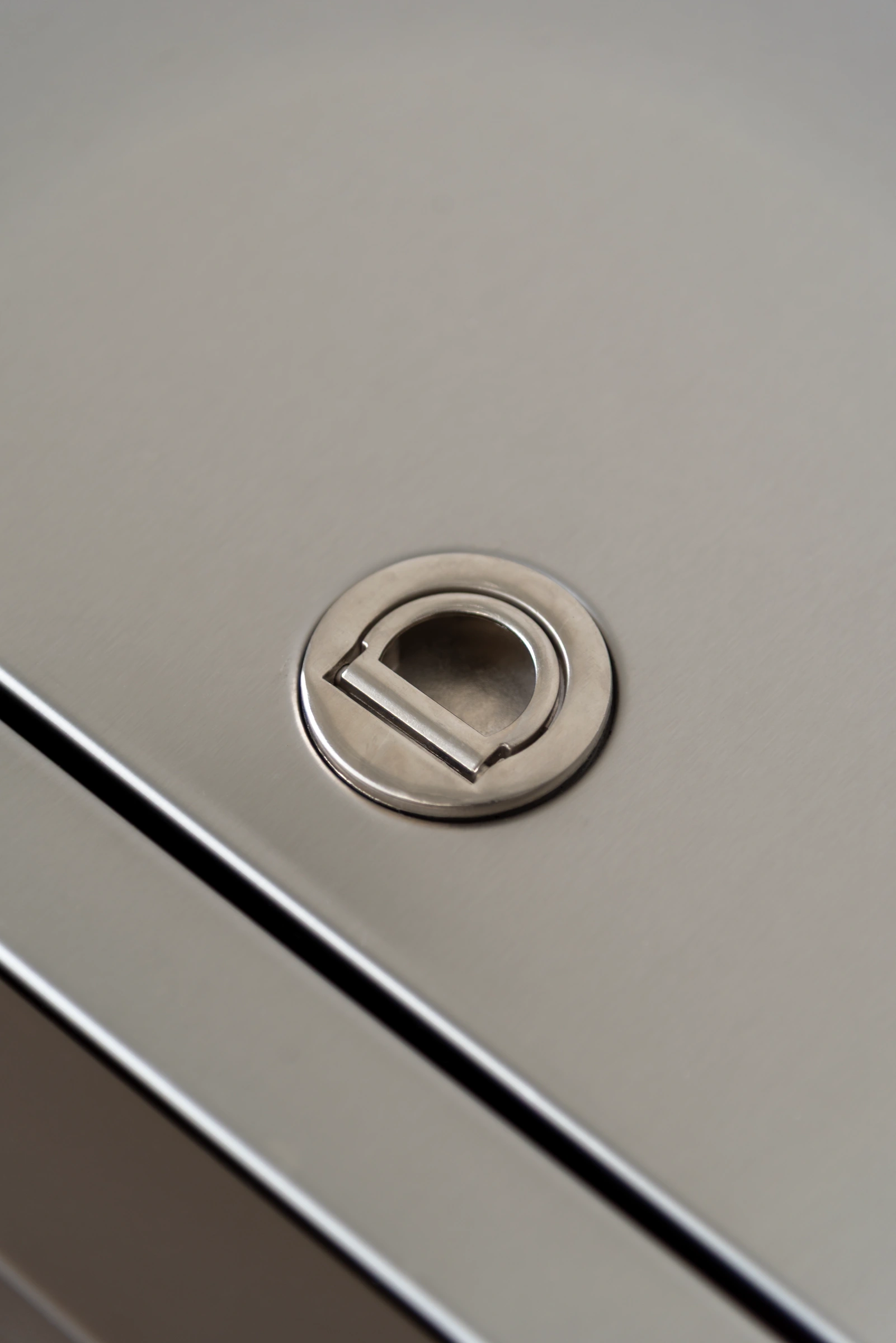 METRO countertop lid and recessed ring pull
For a usable project elevation, show the selected cabinet, the appliance and the finished floor together. Identify the appliance’s support arrangement and the relevant operating surfaces from its documents. Confirm the resulting height with the project team before approval. Raising or lowering a cabinet alone does not resolve every effect on support, adjacent surfaces, openings or service connections.
Compare NOVA and METRO Using Matching Dimension Fields
Compare preparation and sink modules on the same basis
Compare function first, then compare the dimensions that perform that function. NOVA-B and METRO-A both show sink cabinets, but their listed widths and depths differ. NOVA-B is 800 mm wide and 600 mm deep, with the 900/1100 mm surface and rear-panel heights. METRO-A is listed at 900 × 630 × 930 mm. This comparison describes the selected cabinets; it does not establish identical basin sizes, internal spaces or plumbing arrangements.
| Module | Listed width × depth | Working or support level | Separate upper level | Still to confirm for the project |
|---|---|---|---|---|
| NOVA-A storage | 600 × 600 mm | Worktop: 900 mm | Rear panel: 1100 mm | Finished measurement state and opening movement |
| NOVA-B sink | 800 × 600 mm | Worktop: 900 mm | Rear panel: 1100 mm | Sink, fittings and service interfaces |
| NOVA-C preparation and shelving | 800 × 600 mm | Worktop: 900 mm | Rack: 1300 mm | Rack relationship to nearby fixed features |
| METRO-A sink | 900 × 630 mm | Worktop: 930 mm | Not a separate value in this listing | Fittings, projections and service interfaces |
| METRO-D storage | 900 × 630 mm | Worktop: 930 mm | Not a separate value in this listing | Finished measurement state and drawer access |
| NOVA-E lowered base | 755 × 600 mm | Listed cabinet height: 725 mm | Appliance determined separately | Exact appliance and support arrangement |
| METRO-G lowered base | 900 × 630 mm | Listed cabinet height: 730 mm | Appliance determined separately | Exact appliance and support arrangement |
Use this field structure when discussing another series, including URBAN aluminum outdoor kitchen modules or ELITE composite-cabinet outdoor kitchen modules. Retrieve that series’ dimensions rather than carrying the NOVA or METRO values into a new specification.
Compare lowered appliance bases without assuming fit
The difference between NOVA-E and METRO-G is more than their 725 and 730 mm listed heights. Their widths and depths also differ, and an appliance interface may depend on details that are absent from an external dimension list. A small difference in one figure does not prove that the same equipment can be used in both positions.
- METRO-D, 930 mm. The listed height reaches the worktop of this cabinet.
- METRO-G, 730 mm. The listed height describes the lowered module. An installed grill adds its own height and requirements.
Likewise, an open slatted shelf describes a visible storage construction. It does not establish a support rating, appliance mounting arrangement or required ventilation provision. Keep those requirements attached to the actual equipment and its intended installation.
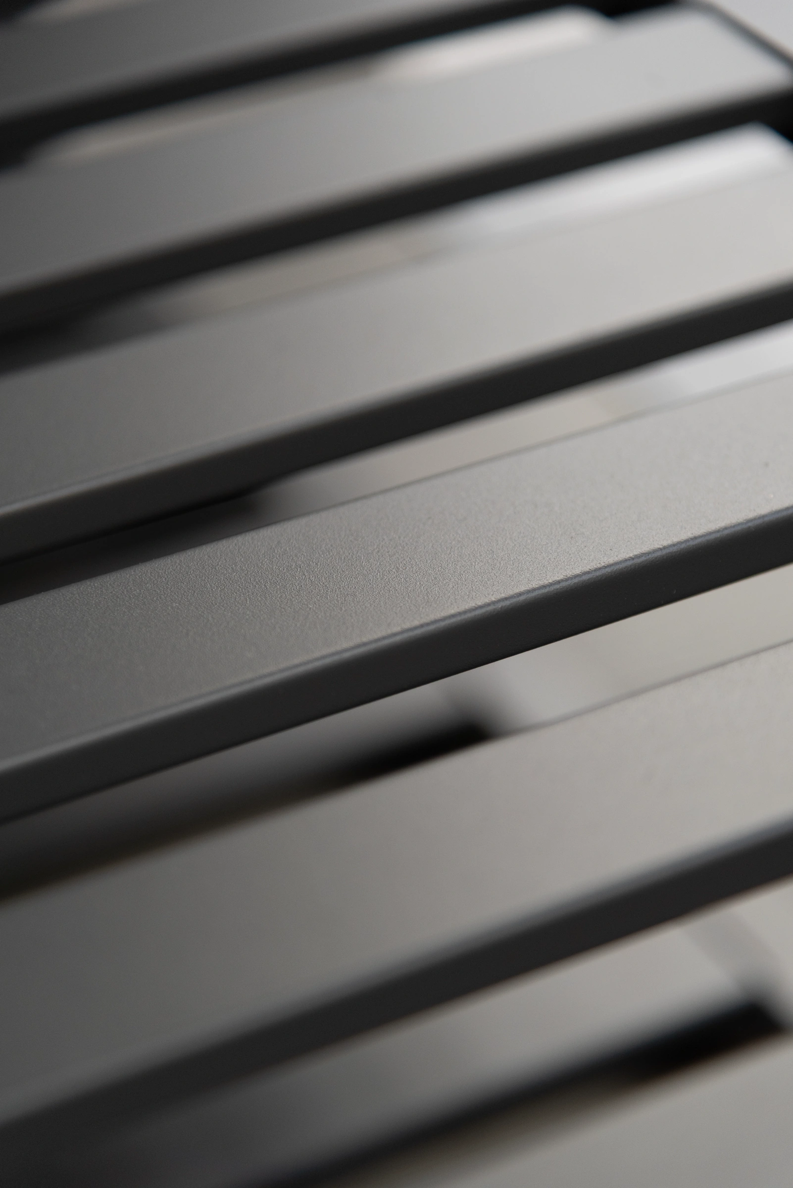 NOVA slatted shelf beneath the preparation area
When speaking with a direct outdoor kitchen manufacturer for dimensioned module schedules, supply the module code beside the questioned dimension. “Confirm METRO-G’s height reference and the selected grill support detail” gives the discussion a definite object. A request to make everything “standard height” leaves the manufacturer and project team to interpret which surface, equipment and finished condition are intended.
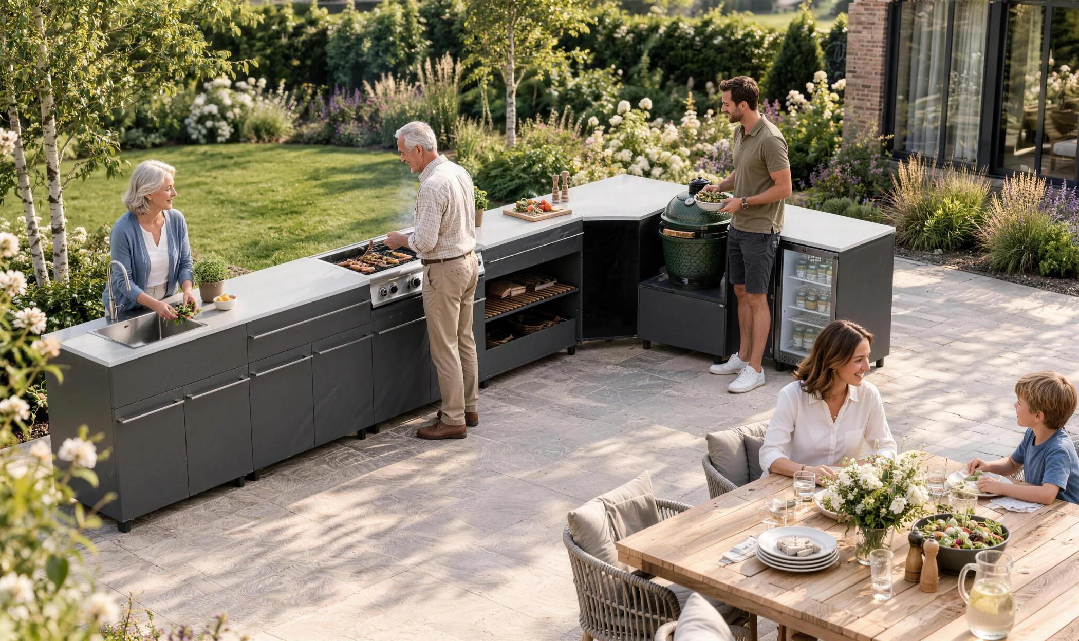 METRO modular outdoor kitchen with an L-shaped work run
Specify Appliance Openings from the Selected Equipment
Separate the appliance body, cutout and support
An appliance body dimension, a cabinet opening and a worktop cutout can all refer to different surfaces. Record them separately and identify which drawing controls each. METRO-L, for example, has a listed external envelope of 600 × 600 × 930 mm. The outside housing width does not establish a 600 mm clear appliance opening: the required opening must be checked against the selected refrigerator and the cabinet detail.
- Known exterior. Record the listed outer W/D/H for METRO-L.
- Opening to confirm. Wₒ and Hₒ are variables. Obtain the applicable internal opening and depth from the selected documents.
- Appliance body. Use the exact selected equipment model and its drawings.
- Opening requirement. The dashed outline represents a separate information field, not a dimensioned OCC opening.
- Use and access. Confirm door or lid movement, ventilation and service access separately. The arrow does not state a required clearance.
Equipment manuals demonstrate why this separation matters. The Weber built-in installation guide for its specified Summit models identifies finished surfaces as dimensional references and separates cutout information from installation clearances. Its values apply to the appliances and installation conditions covered by that guide. They are not dimensions for an unspecified grill or proof of compatibility with an OCC module.
For the project record, identify the appliance model, the applicable manual revision and any required fabrication drawing. Our guide to grill, kamado and refrigerator integration before ordering covers the checks that follow these dimensions. Then record the opening shape, support reference and related conditions from those sources. A photograph showing a grill in a cabinet is useful context, but cannot replace this dimensional information or confirm what equipment is included in an order.
Record ventilation, movement and service requirements
A device can occupy an opening while still needing space for airflow, movement or maintenance. These requirements may occur in different directions. A lid moves above and behind the equipment; a refrigerator door needs an opening path; service access may require removal or an approach from a particular side. A single rectangle on a floor plan cannot explain all three.
The Whirlpool undercounter refrigerator guide illustrates separate fields for the opening, leveling-leg condition, door movement and ventilation. It is a documentation example, not an appliance recommendation or an approval for outdoor use. Use the corresponding documents for the actual refrigerator selected for the kitchen.
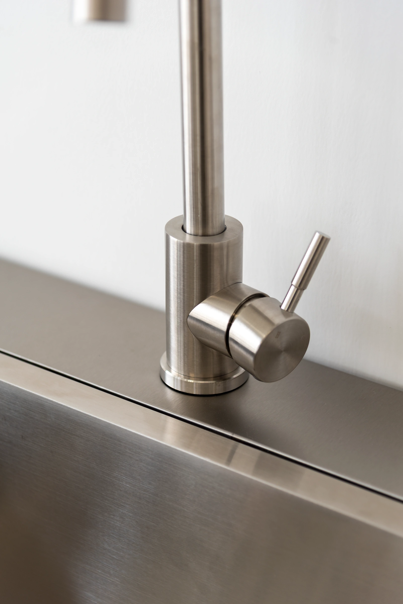 METRO faucet, sink and adjoining worktop
Apply the same discipline to a sink position. The cabinet dimensions, tap height, basin arrangement and service route describe different objects. Identify each required reference without assuming that the cabinet’s top is the highest installed point. Where an equipment or connection detail is not yet available, keep that specific field pending and assign who will obtain it. This makes the information gap visible without replacing it with an assumed allowance.
Check the Selected Assembly and Its Operating Space
Trace straight runs and L-shaped returns on a plan
Move from the module register to one identified arrangement. Mark the front of each cabinet, the direction of the run and the location of the return. The NOVA examples below retain the different positions of storage, sink, corner and lowered bases. Their purpose here is to show where dimensions belong when an arrangement changes.
- NOVA-F lowered kamado base. Keep the platform and back-panel heights separate from the illustrated appliance.
- NOVA-A storage cabinet. Record the worktop level separately from the raised back-panel height.
- NOVA-B sink cabinet. Record the cabinet envelope and confirm the sink and faucet details separately.
- NOVA-D corner module. Read the two plan legs and the angled frontage on the configuration drawing.
- NOVA-C preparation and rack module. The worktop and the top of the tool rack have different height references.
- NOVA-E lower barbecue base. The base-cabinet height does not include the illustrated grill above it.
- NOVA-A storage cabinet. Record the worktop level separately from the raised back-panel height.
- NOVA-E lower barbecue base. The base-cabinet height does not include the illustrated grill above it.
- NOVA-A storage cabinet. Record the worktop level separately from the raised back-panel height.
- NOVA-B sink cabinet. Record the cabinet envelope and confirm the sink and faucet details separately.
- NOVA-D corner module. Read the two plan legs and the angled frontage on the configuration drawing.
- NOVA-C preparation and rack module. The worktop and the top of the tool rack have different height references.
- NOVA-A storage cabinet. Record the worktop level separately from the raised back-panel height.
- NOVA-E lower barbecue base. The base-cabinet height does not include the illustrated grill above it.
- NOVA-A storage cabinet. Record the worktop level separately from the raised back-panel height.
- NOVA-B sink cabinet. Record the cabinet envelope and confirm the sink and faucet details separately.
- NOVA-C preparation and rack module. The worktop and the top of the tool rack have different height references.
- NOVA-A storage cabinet. Record the worktop level separately from the raised back-panel height.
- NOVA-B sink cabinet. Record the cabinet envelope and confirm the sink and faucet details separately.
- NOVA-E lower barbecue base. The base-cabinet height does not include the illustrated grill above it.
The METRO examples show another series’ arrangements, including straight runs and returns. Keep that series’ codes and shapes together. For the fourth example, confirm the corner worktop element on the selected configuration drawing before preparing an order list or overall dimensions; its appearance alone does not establish the module code.
- METRO-D drawer and storage cabinet. Record the cabinet size and the separate space needed to use the fronts.
- METRO-G lower barbecue base. The lower cabinet height does not establish the completed cooking height.
- METRO-D drawer and storage cabinet. Record the cabinet size and the separate space needed to use the fronts.
- METRO-A sink cabinet. Record the cabinet envelope separately from the faucet and other fittings.
- METRO-F lowered kamado base. The platform and raised back panel are separate height references.
- METRO-L refrigeration housing. The external housing size does not define the clear appliance opening.
- METRO-L refrigeration housing. The external housing size does not define the clear appliance opening.
- METRO-A sink cabinet. Record the cabinet envelope separately from the faucet and other fittings.
- METRO-D drawer and storage cabinet. Record the cabinet size and the separate space needed to use the fronts.
- METRO-F lowered kamado base. The platform and raised back panel are separate height references.
- METRO-L refrigeration housing. The external housing size does not define the clear appliance opening.
- METRO-C flush cooking cabinet. Confirm the selected cooking equipment and its interface on the applicable drawing.
- METRO-A sink cabinet. Record the cabinet envelope separately from the faucet and other fittings.
- METRO-E open corner shelving. Read both plan legs and the angled front on the selected configuration drawing.
- METRO-F lowered kamado base. The platform and raised back panel are separate height references.
- METRO-D drawer and storage cabinet. Record the cabinet size and the separate space needed to use the fronts.
- METRO-G lower barbecue base. The lower cabinet height does not establish the completed cooking height.
- METRO-D drawer and storage cabinet. Record the cabinet size and the separate space needed to use the fronts.
- METRO-A sink cabinet. Record the cabinet envelope separately from the faucet and other fittings.
- Corner worktop shown. This turn is identified by function. Confirm its specification on the selected configuration drawing.
- METRO-F lowered kamado base. The platform and raised back panel are separate height references.
- METRO-L refrigeration housing. The external housing size does not define the clear appliance opening.
For an L shape, identify each leg’s finished extent and the corner reference. Adding every listed width into one total loses the change of direction and can obscure how the corner occupies both runs. Our straight-line and L-shaped outdoor kitchen layout comparison discusses the layout trade-offs. Once a layout is chosen, use its dimensioned plan to establish the actual outline, end conditions and relationship to the site.
Check doors, drawers, lids and service access
After marking the closed outline, add the spaces needed to use and maintain the kitchen. Show which drawer opens toward the working area, which door approaches an adjoining return and where an appliance must remain accessible. Handles and other projections also deserve their own reference when they affect a nearby object or route.
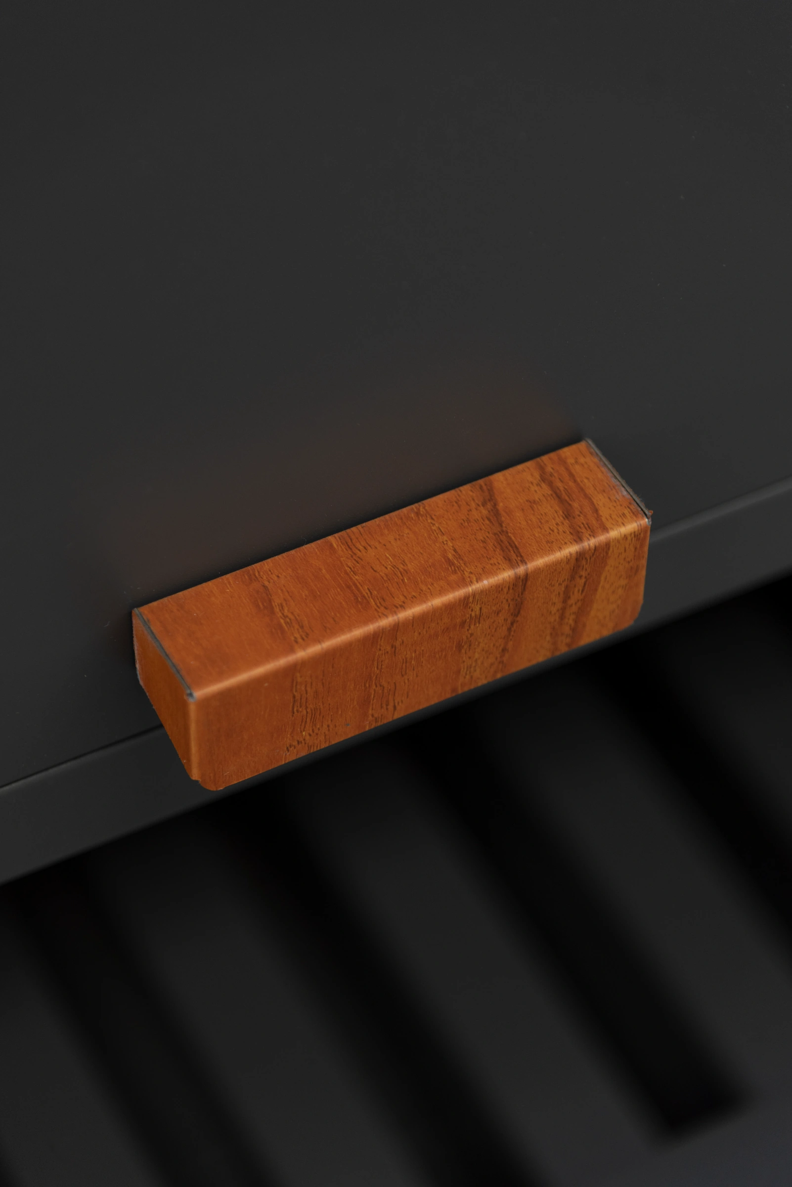 NOVA handle projecting from the cabinet front
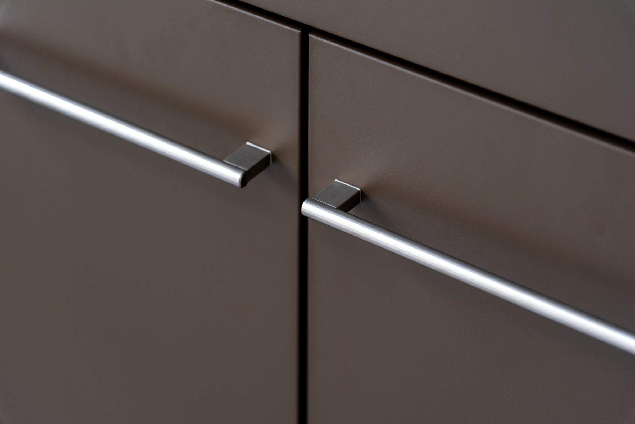 METRO cabinet handles below the worktop
A practical review follows an ordinary task: open the storage cabinet, stand at the preparation surface, use the sink and approach the cooking position. Repeat it with a second person moving through the proposed space. This tests whether the drawing has considered simultaneous use; it does not establish a universal aisle dimension or replace applicable project requirements.
Also consider the less frequent tasks. An appliance may need servicing while adjacent modules remain installed, and a lid may need a different space when open. Record the equipment requirements and the planned access route. If a fixed wall, step or another product affects that route, show it on the same site plan rather than leaving the coordination to a separate photograph.
Build a Traceable Module Dimension Schedule
Record units, document revisions and confirmation status
A useful module schedule connects each figure to an identifiable source. Choose the governing unit for the project and keep any secondary conversion clearly labeled. NIST’s length-unit reference provides the unit relationships; conversion does not create a manufacturing tolerance or increase the precision of the original figure.
The source matrix below shows where to begin. “Primary” identifies the starting source for the field; “Check” means reconcile that information with the other document or project condition. It allocates information for review rather than approving a fit.
| Dimension or record field | Module or assembly drawing | Exact appliance documents | Site or order confirmation |
|---|---|---|---|
| Series, module code and quantity | Primary | Check | Check |
| External W/D/H and height objects | Primary | Check | Check |
| Appliance identity and manual revision | Check | Primary | Check |
| Cutout, support and ventilation requirements | Check | Primary | Check |
| Finished arrangement, ends and projections | Primary | Check | Check |
| Finished floor and nearby fixed features | Check | Check | Primary |
| Opening movement and service access | Check | Primary | Check |
| Units, document revisions and confirmation status | Check | Check | Primary |
Keep a revised dimension attached to its module and drawing revision. Otherwise, a correct replacement value can still be applied to the wrong arrangement. When several kitchens are ordered, identify which configurations share the same record and which require separate sheets. A distributor preparing two arrangements with the same sink module can retain its module reference, while still checking the different sink position, adjoining corner and service route in each plan. Shared parts reduce repeated information; they do not remove the need to identify the assembly in which each part will be used. The schedule should make those differences visible rather than hiding them behind a single description of the product range.
Resolve missing interface information before drawing approval
Separate a confirmed cabinet dimension from an unconfirmed appliance interface. The cabinet manufacturer, equipment supplier and project design or installation team contribute different information. Allocate the open questions to the party able to answer them, then bring the resolved details back onto the selected configuration drawing.
At the Outdoor Creation manufacturing facility, we manufacture directly; the project discussion must still identify the selected product and its intended equipment. Working with a modular outdoor kitchen factory for project specification coordination is most effective when the module schedule and appliance documents refer to the same arrangement and revision.
If the kitchen is part of a wider plan involving outdoor product systems for coordinated projects, keep the kitchen’s references visible within that plan. Nearby structures and other products do not automatically share compatible dimensions or connections. Finally, attach the resolved dimension record to the broader outdoor kitchen RFQ information for modules and appliances. This gives the commercial discussion a defined technical basis and shows exactly which details still need confirmation before the drawing is approved.
Frequently Asked Questions
Are all outdoor kitchen cabinets the same height?
No. Worktop, appliance-support and upper-panel heights differ by module and series. Compare the same measurement references on the selected drawings rather than treating every listed height as a working surface.
Which dimensions matter when choosing outdoor kitchen modules?
Record width, depth and each relevant height, then check the assembled outline, appliance interfaces and operating spaces. Identify the series, module, units and drawing revision beside the figures.
Does cabinet width equal the appliance cutout width?
No. Cabinet width describes an external dimension. Use the selected appliance documents and applicable fabrication drawing to establish its opening, cutout, support and related installation requirements.
Do module widths add up to the finished run?
Not automatically. End conditions, projections and corner geometry can affect the finished outline. Confirm each run and return on the selected configuration drawing.
Can a customer swap the grill later?
Only after reassessment. Check the replacement model’s opening, support, ventilation and operating requirements against the cabinet and site. Similar external dimensions do not establish compatibility.
What belongs in an outdoor kitchen module schedule?
Include configuration and module identities, dimension directions, height references, units, document revisions, appliance interfaces, responsibilities and confirmation status. Keep unresolved information visible and linked to its source.
Dimensions, materials, hardware, appliance interfaces and installation requirements depend on the selected configuration. Projects can be customized; available customization options and final specifications must be confirmed for the specific project and order.